Shaft body machining tool

A shaft and tooling technology, applied in metal processing equipment, metal processing mechanical parts, positioning devices, etc., can solve the problems of easy rotation of the shaft, high cost, affecting the processing effect of the shaft, etc., and achieve good positioning effect and tooling. simple structure

Inactive Publication Date: 2017-01-04
天津世创机械制造有限公司
View PDF8 Cites 0 Cited by
  • Summary
  • Abstract
  • Description
  • Claims
  • Application Information

AI Technical Summary

Problems solved by technology

[0002] Shaft products are indispensable and important parts for the connection between various parts in the industry. When processing the shaft, it is necessary to make grooves on the end face or the peripheral surface of the shaft. When the current lathe clamps the shaft body, the shaft The cost of body tooling is relatively high, and if the tool exerts too much force on the shaft body, the shaft body will easily rotate, which will affect the processing effect of the shaft body

Method used


Image

  • Shaft body machining tool

Examples


Embodiment Construction

[0013] In order to have a further understanding and understanding of the structural features of the present invention and the achieved effects, the preferred embodiments and accompanying drawings will be used for a detailed description, as follows:

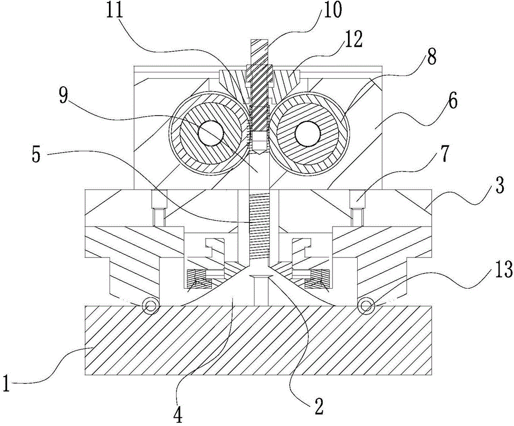
[0014] Such as figure 1 As shown, a shaft processing tooling includes a lathe base 1 and a tool 2 arranged on the lathe base 1. A shaft fixing plate 3 is provided on the lathe base 1, and a tool 2 is provided at the bottom of the shaft fixing plate 3. The protruding cavity 4 is provided with a shaft placement cavity 5 communicating with it above the cavity 4;

[0015] A shaft positioning plate 6 that can be lifted is arranged above the shaft fixing plate 3, and the shaft positioning plate 6 is connected with the shaft fixing plate 3 through a cylinder 7. There are two cylinders 7, which are respectively located on the shaft fixing plate 3. Two rotating wheels 8 are arranged in the shaft body positioning plate 6, and the two rotat...


PUM


Abstract

The invention relates to a shaft body machining tool. The shaft body machining tool comprises a lathe base and a cutter arranged on the lathe base. A shaft body fixing plate is arranged on the lathe base. A shaft body mounting cavity is formed in the bottom of the shaft body fixing plate. A shaft body positioning plate is arranged on the shaft body fixing plate. Two rotating wheels are arranged inside the shaft body positioning plate. A vertical positioning channel is formed between the two rotating wheels. A positioning rod is arranged in the positioning channel. The positioning channel formed in the shaft body positioning plate and the shaft body mounting cavity formed in the shaft body fixing plate are located on the same straight line. The end of the positioning rod corresponds to the shaft body mounting cavity. When the cutter below the shaft body fixing plate is used for machining a shaft body, the two rotating wheels on the shaft body positioning plate drive the positioning rod engaged with the two rotating wheels to move downwards and stretch into the shaft body mounting cavity to abut against the end of the to-be-machined shaft body, so that the to-be-machined shaft body is positioned; and when the cutter on the lathe base is used for machining the shaft body, the shaft body cannot rotate or loose; and the tool is simple in structure and good in shaft body positioning effect.

Description

technical field [0001] The invention relates to a shaft body processing tool. Background technique [0002] Shaft products are indispensable and important parts for the connection between various parts in the industry. When processing the shaft, it is necessary to make grooves on the end face or the peripheral surface of the shaft. When the current lathe clamps the shaft body, the shaft The cost of body tooling is relatively high, and if the tool exerts too much force on the shaft body, the shaft body will easily rotate, which will affect the processing effect of the shaft body. Contents of the invention [0003] The object of the present invention is to provide a tool for machining shafts in order to solve the defects existing in machining shafts on a lathe in the prior art. [0004] In order to achieve the above object, the technical scheme adopted in the present invention is: [0005] A tool for machining a shaft, comprising a lathe base and a tool set on the lathe ba...

Claims


Application Information

Patent Timeline
Patent Type & Authority Applications(China)
IPC IPC(8): B23B5/08B23B15/00
CPCB23B5/08B23Q3/064B23Q3/08B23Q2703/04
Inventor 齐志亮单晓东
Owner 天津世创机械制造有限公司
Why Eureka
Try Eureka