Steel tube cutter

A cutting machine and steel pipe technology, applied in the field of machinery, can solve the problem that the cutting machine can only cut steel pipes of the same diameter, and achieve the effects of compact structure, reasonable design, and improved practicability

Inactive Publication Date: 2017-01-04
俞彩红
View PDF0 Cites 27 Cited by
  • Summary
  • Abstract
  • Description
  • Claims
  • Application Information

AI Technical Summary

Problems solved by technology

[0004] The object of the present invention is to provide a steel pipe cutting machine, which has the advantage of being able to cut steel

Method used


Image

  • Steel tube cutter
  • Steel tube cutter
  • Steel tube cutter

Examples


Embodiment Construction

[0020] The following will clearly and completely describe the technical solutions in the embodiments of the present invention with reference to the accompanying drawings in the embodiments of the present invention. Obviously, the described embodiments are only some, not all, embodiments of the present invention. Based on the embodiments of the present invention, all other embodiments obtained by persons of ordinary skill in the art without making creative efforts belong to the protection scope of the present invention.

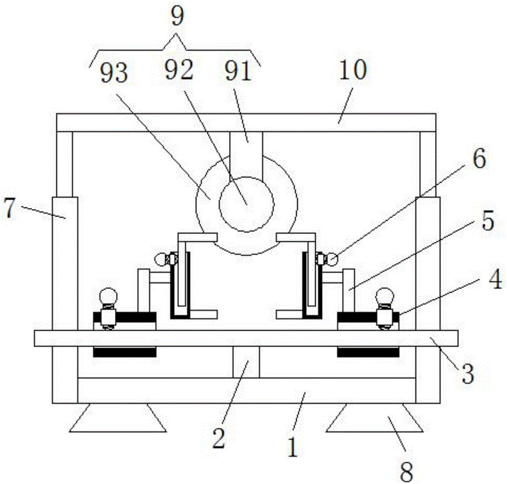
[0021] see figure 1 , the present invention provides a technical solution: a steel pipe cutting machine, including a base plate 1, four support feet 8 are arranged on the lower surface of the base plate 1, and the top ends of the four support feet 8 are respectively fixedly connected to the four corners of the lower surface of the base plate 1 , by setting four supporting feet 8, the placement of the cutting machine is made more stable, the upper surface of th...


PUM


Abstract

The invention discloses a steel tube cutter. The steel tube cutter comprises a baseplate, wherein a support bar is fixedly connected to the upper surface of the baseplate; the top end of support bar is fixedly connected with a round bar; two sliding devices are connected to the surface of the round bar in a sleeving manner; the upper surfaces of the two sliding devices are fixedly connected with the side surfaces of two fixing devices through two connecting devices respectively; electric telescopic bars are fixedly connected to the side surface of the baseplate; the tops of the electric telescopic bars are fixedly connected with a cross bar; the lower surface of the cross bar is fixedly connected with a cutting device; each sliding device comprises a round sleeve; the upper surface of each round sleeve is connected with a first threaded cap in a clamping manner. According to the steel tube cutter, slide bars and the two sliding devices work together to adjust the distance between the two fixing devices; as the fixing devices are arranged, the distances between two first clamp bars and two second clamp bars can be adjusted, accordingly, the steel tube cutter can cut steel tubes with different diameters, and the practicability of the steel tube cutter is improved.

Description

technical field [0001] The invention relates to the technical field of machinery, in particular to a steel pipe cutting machine. Background technique [0002] With the development of modern mechanical processing industry, the requirements for cutting quality and precision are constantly improving, and the requirements for improving production efficiency, reducing production costs and having highly intelligent automatic cutting functions are also increasing. The development of CNC cutting machines must adapt to the requirements of the development of modern machining industry. Cutting machines are divided into flame cutting machines, plasma cutting machines, laser cutting machines and water cutting machines. The laser cutting machine has the fastest efficiency, the highest cutting precision, and the cutting thickness is generally small. The cutting speed of the plasma cutting machine is also very fast, and the cutting surface has a certain slope. The flame cutting machine i...

Claims


Application Information

Patent Timeline
IPC IPC(8): B23D19/00B23D33/02
CPCB23D19/00B23D33/02
Inventor 俞彩红
Owner 俞彩红
Why Eureka
Try Eureka