Dresser for deep hole internal thread
An internal thread and dresser technology, applied in the field of hand tools, can solve the problems of inability to perform complete repair, easily damaged thread profile, low dressing efficiency, etc., and achieves the effect of ensuring reliability, ensuring consistency, and improving work efficiency
- Summary
- Abstract
- Description
- Claims
- Application Information
AI Technical Summary
Problems solved by technology
Method used
Image

Examples
Embodiment Construction
[0032] The present invention will be further described below in conjunction with the accompanying drawings and specific embodiments.
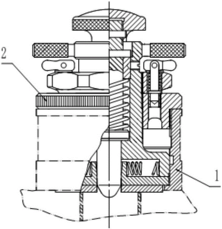
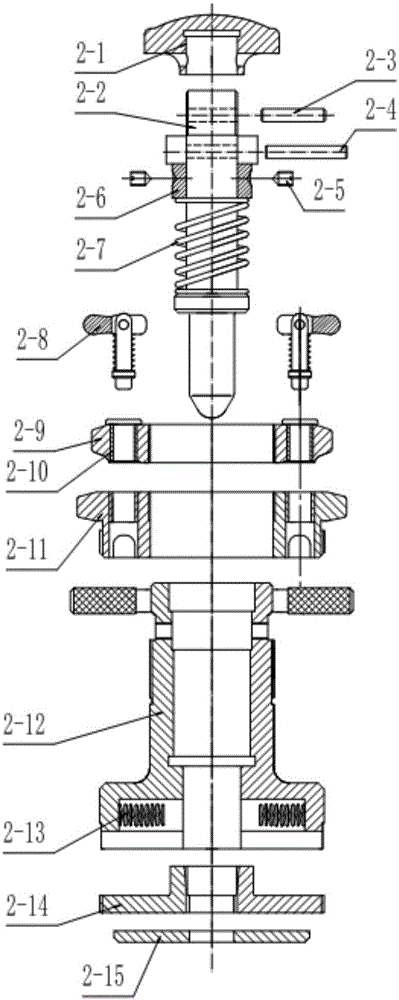
[0033] see figure 2 , image 3 , Figure 4 , the present invention is a deep hole internal thread trimmer 2, which includes a positioning mandrel 2-2, a ferrule 2-6, a thread cutter 2-14, a solid seat 2-12, a solid sleeve 2-11 and a baffle plate 2 -15; the positioning mandrel 2-2 penetrates into the inner cavity of the fixed seat 2-12, and a conical surface 2-2-1 that cooperates with the thread cutter 2-14 is provided at the lower end of the positioning mandrel 2-2; The baffle plate 2-15 is fixedly installed on the bottom of the solid seat 2-12, and the baffle plate 2-15 is provided with a positioning mandrel passing hole.
[0034] see figure 2 , image 3 , Figure 5 , in the deep hole internal thread trimmer 2, the ferrule 2-6 is a stepped sleeve structure, embedded in the inner cavity of the solid seat 2-12, and locked and positioned ...
PUM
 Abstract
Description
Claims
Application Information
 - R&D
- Intellectual Property
- Life Sciences
- Materials
- Tech Scout
- Unparalleled Data Quality
- Higher Quality Content
- 60% Fewer Hallucinations
Browse by: Latest US Patents, China's latest patents, Technical Efficacy Thesaurus, Application Domain, Technology Topic, Popular Technical Reports.
© 2025 PatSnap. All rights reserved.Legal|Privacy policy|Modern Slavery Act Transparency Statement|Sitemap|About US| Contact US: help@patsnap.com