

A connection method between pdc and cemented carbide
A technology of cemented carbide and connection method, which is applied in welding equipment, metal processing equipment, welding/welding/cutting items, etc., can solve the problems of weakening PCDPDC performance and affecting the quality of PDC composite sheets, and achieves low manufacturing cost and practical effect. Good, low melting temperature effect
- Summary
- Abstract
- Description
- Claims
- Application Information
AI Technical Summary
Problems solved by technology
Method used
Image

Examples
Embodiment approach
[0033] One, a kind of connection method of PDC and cemented carbide, comprises the following steps:
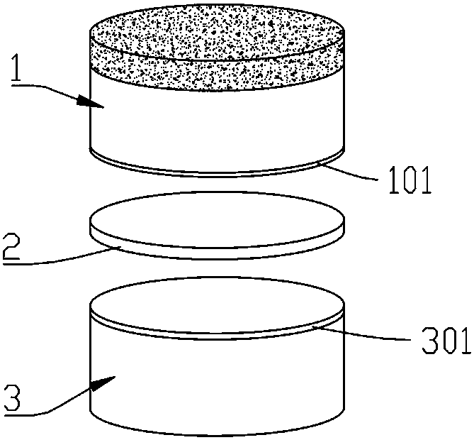
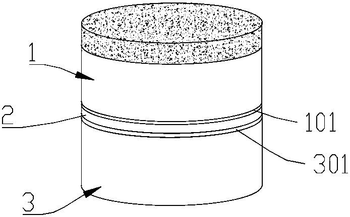
[0034] a. Cleaning: Put PDC1 and cemented carbide 3 into an ultrasonic cleaner for 10-15 minutes, and dry them with a hair dryer after cleaning;
[0035] b. Surface modification: use the method of surface modification to modify the connected surface of PDC1 and cemented carbide 3, so that the nickel-plated layer is formed on the connected surface. Wherein, the non-PCD end of the PDC is the connected surface. After modification, a nickel-plated layer, 101, is formed at one end of the PDC1, and a nickel-plated layer II301 is formed at one end of the cemented carbide 3. In order to prevent the PCD at the upper end of PDC1 from being damaged by heat, the connected surface of PDC1 cannot be modified by surface modification at a higher temperature, and nickel plating can be used on the connected surface by electroplating or other methods. The cemented carbide 3 has a high abilit...
Embodiment 1
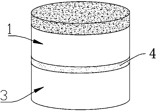
[0049] Put the PDC and cemented carbide into the ultrasonic cleaning machine to clean for 15 minutes, and dry it with a hair dryer after cleaning; the non-PCD end of the PDC is the connected surface, and the connected surface is plated with a layer of 0.2mm thick Nickel-plated layer, a 0.2mm-thick nickel-plated layer is plated on the surface of the hard alloy to be connected by thermal spraying. The nickel-plated layer on the PDC is opposite to the nickel-plated layer on the hard alloy, and a layer of Ag75Cu solder is placed between the nickel-plated layer and the nickel-plated layer (Ag75Cu refers to the weight of silver accounting for 75%, the weight of copper 25% solder alloy). Put the assembled PDC, brazing filler metal and cemented carbide upright into the vacuum furnace, and the vacuum degree in the vacuum furnace reaches 10 -1 After MPa, start heating, and heat up to 800° C. at a heating rate of 5° C. / min, and 800° C. is the highest heating temperature in this embodim...
Embodiment 2
[0052] Clean the PDC and hard alloy in an ultrasonic cleaning machine for 10 minutes, and dry it with a hair dryer after cleaning; use electroplating to plate a layer of nickel-plated layer I with a thickness of 0.15mm on the non-PCD end of the PDC. One end is coated with a 0.15mm thick nickel layer II by thermal spraying. The nickel-plated layer I on the PDC is opposite to the nickel-plated layer II on the hard alloy, and a layer of Ag72Cu eutectic solder is placed between the nickel-plated layer I and the nickel-plated layer II. Put the assembled PDC, brazing filler metal and cemented carbide upright into the vacuum furnace, and the vacuum degree in the vacuum furnace reaches 10 -3 Start heating after MPa, and heat to 779°C at a heating rate of 10°C / min (the eutectic temperature of the AgCu eutectic solder may vary depending on the furnace and the slight difference in the composition of the solder), and hold for 3 minutes. Then lower the furnace temperature to 680°C, keep ...
PUM
| Property | Measurement | Unit |
|---|---|---|
| thickness | aaaaa | aaaaa |
| thickness | aaaaa | aaaaa |
| thickness | aaaaa | aaaaa |
Abstract
Description
Claims
Application Information