
Ultrasonic welding machine and its ultrasonic welding control method

An ultrasonic welding machine and ultrasonic welding technology, applied in welding equipment, manufacturing tools, non-electric welding equipment, etc., can solve the problems of long welding processing cycle, low operation efficiency, and inaccurate rotation angle, etc. Efficiency improvement, good use effect

Active Publication Date: 2019-05-10
SHENZHEN TECHSON AUTOMATION SYST
View PDF13 Cites 1 Cited by
  • Summary
  • Abstract
  • Description
  • Claims
  • Application Information

AI Technical Summary

Problems solved by technology

[0005] Specifically, on the one hand, the ultrasonic welding machine with this structure can only perform a single operation on a single workpiece. After welding a single workpiece, it needs to be shut down to install a new workpiece to be welded, and then restarted to install the new workpiece. The corresponding welding position on the rear side of the workpiece and the corresponding welding position on the front side of the workpiece are ultrasonically welded. In this way, even if the welding operation is not coherent and does not have continuity, the operation efficiency is low and the welding process cycle is long. On the other hand, in its corresponding In the welding operation mode, after taking pictures of the welding position on the front side of the corresponding workpiece, it is necessary to rotate the corresponding rotary platform, and then perform ultrasonic welding on the welding position after taking pictures of the front side of the corresponding workpiece, and when rotating the corresponding rotary platform, the corresponding The rotation angle of the rotary platform is more or less inaccurate, so that there will be a deviation between the actual welding position on the front side of the corresponding workpiece and the welding position after the photo positioning, and then, the welding position coordinates of the corresponding ultrasonic welding head compared with the photo positioning When the corresponding workpiece is ultrasonically welded, there is a problem that the welding position is offset, so that even if there are defective welding products

Method used


Image

  • Ultrasonic welding machine and its ultrasonic welding control method
  • Ultrasonic welding machine and its ultrasonic welding control method
  • Ultrasonic welding machine and its ultrasonic welding control method

Examples


Embodiment 1

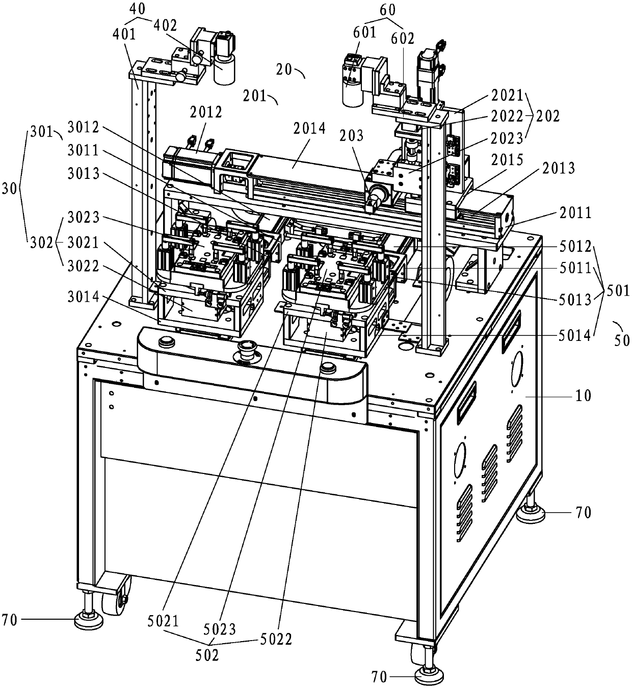
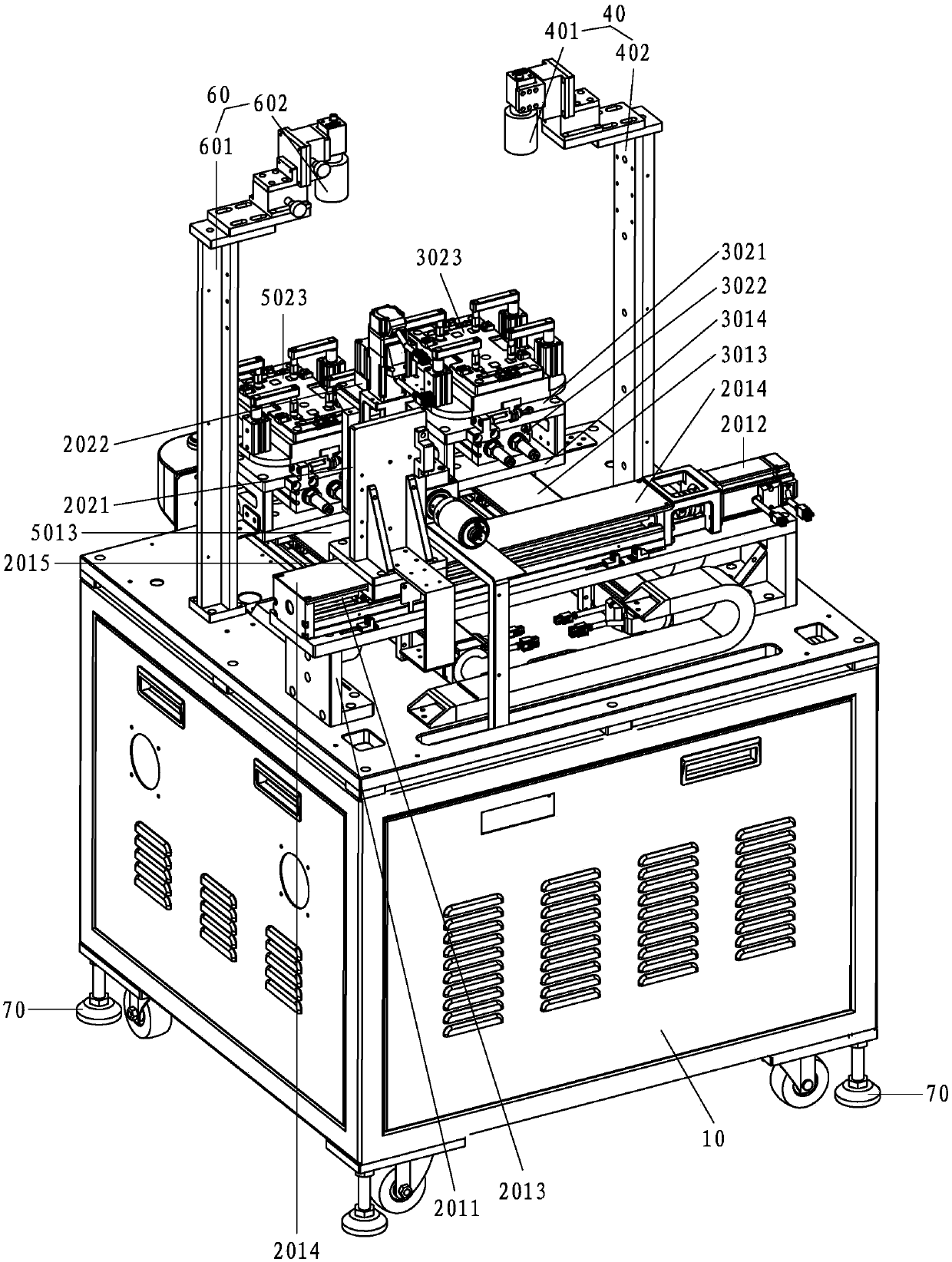
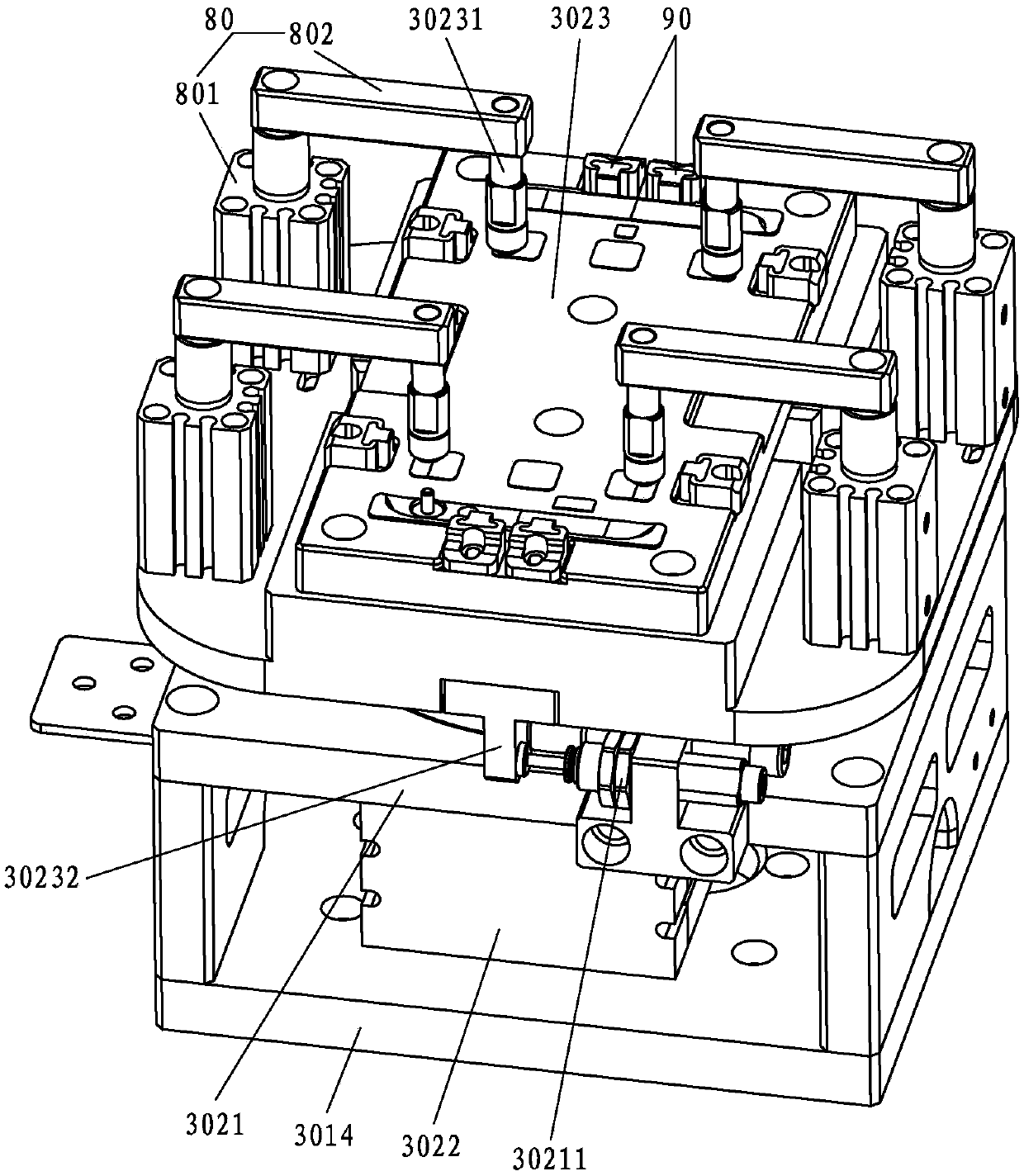
[0081] combine figure 1 , figure 2 , image 3 , Figure 4 shown;

[0082] An ultrasonic welding machine provided by the present invention includes a frame 10 and a main controller arranged in the frame 10. The improvement of the present invention is that it also includes:

[0083]The ultrasonic welding mechanism 20, the ultrasonic welding mechanism 20 includes a horizontal translation mechanism 201 arranged on the rear end of the upper end surface of the frame 10 along the horizontal direction, and a vertical lifting mechanism fixed on the horizontal translation mechanism 201 along the vertical direction 202 and the ultrasonic welding head 203 fixed on the vertical lifting mechanism 202 along the longitudinal direction; the horizontal translation mechanism 201, the vertical lifting mechanism 202 and the ultrasonic welding head 203 are respectively connected with the main controller signal , and the ultrasonic welding head 203 faces to the front and upper side of the frame...

Embodiment 2

[0120] refer to Figure 1-Figure 4 shown;

[0121] An ultrasonic welding control method provided by the present invention is applied to the ultrasonic welding machine described in Embodiment 1, which includes the following steps:

[0122] S1. Control the first longitudinal translation mechanism 301 through the main controller, so that the first rotating platform 302 moves along the first longitudinal translation mechanism 301 to directly below the first CCD camera;

[0123] S2. Use the first CCD camera 402 to photograph and locate the welding position of the rear side of the workpiece clamped on the first rotating platform 302, and send the welding position information after photographing and positioning the rear side of the relevant workpiece to the the main controller;

[0124] S3. Control the first longitudinal translation mechanism 301 through the main controller, so that the first rotating platform 302 moves along the first longitudinal translation mechanism 301 to dire...


PUM


Abstract

The invention discloses an ultrasonic welding machine and an ultrasonic welding control method thereof. The ultrasonic welding machine comprises a machine frame, a main controller, an ultrasonic welding mechanism, a first workpiece pressing and fixing mechanism, a first CCD image pickup mechanism, a second workpiece pressing and fixing mechanism and a second CCD image pickup mechanism. The ultrasonic welding mechanism comprises a transverse translation mechanism, a vertical lifting mechanism and an ultrasonic welding head. The first workpiece pressing and fixing mechanism comprises a first longitudinal translation mechanism and a first rotary platform. The second workpiece pressing and fixing mechanism comprises a second longitudinal translation mechanism and a second rotary platform. The ultrasonic welding machine has the beneficial effects that the ultrasonic welding mechanism can weld a workpiece on the first rotary platform and a workpiece on the second rotary platform in sequence, welding is circulated and repeated, and the ultrasonic welding machine works intermittently, so that the welding efficiency can be greatly improved. By means of the ultrasonic welding control method provided by the invention, welded positions are accurate and free of deviation, thus, defective welded products can be greatly decreased, and the welding quality also can be greatly improved.

Description

technical field [0001] The invention relates to the technical field of ultrasonic welding equipment, in particular to an ultrasonic welding machine and an ultrasonic welding control method thereof. Background technique [0002] At this stage, in the mobile phone manufacturing process, it is usually necessary to weld the copper sheets inside the mobile phone, that is, to position the corresponding copper sheets according to the welding points of the copper sheets to be welded, and then weld the corresponding copper sheets with the ultrasonic welding head of the ultrasonic welding machine Point contact for welding operations. [0003] The traditional ultrasonic welding machine generally includes an ultrasonic welding mechanism, a welding positioning device and a CCD camera mechanism. The corresponding welding positioning device generally includes a longitudinal movement mechanism fixed on the frame platform and perpendicular to the transverse movement mechanism of the corresp...

Claims


Application Information

Patent Timeline
Patent Type & Authority Patents(China)
IPC IPC(8): B23K20/10
CPCB23K20/10
Inventor 马力张勇
Owner SHENZHEN TECHSON AUTOMATION SYST
Learn More