Automatic vertical centrifugal dewatering machine

A vertical centrifuge and dehydrator technology, applied in non-progressive dryers, dryers, drying solid materials, etc., can solve the problems of affecting the dehydration effect, fixed distance, waste of power, etc., to optimize the drying effect and improve The effect of work efficiency

Inactive Publication Date: 2019-04-12
李文博
View PDF1 Cites 1 Cited by
  • Summary
  • Abstract
  • Description
  • Claims
  • Application Information

AI Technical Summary

Problems solved by technology

Moreover, the materials that can be dehydrated each time in the dehydration cylinder are limited, and the dehydrated semi-dry materials are easy to adhere to the inner wall of the dehydration cylinder, which wastes power and affects the dehydration effect of subsequent added materials.
[0003] The Chinese invention patent with the publication number CN202316127 discloses a potato powder and slag crushing and dehydration separation device. The scraper can clean the material inside the sieve basket. The situation where the dehydrated material is cleaned by the scraper
Although continuous work is achieved, the dehydration effect is affected

Method used


Image

  • Automatic vertical centrifugal dewatering machine
  • Automatic vertical centrifugal dewatering machine
  • Automatic vertical centrifugal dewatering machine

Examples


Embodiment 1

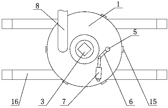
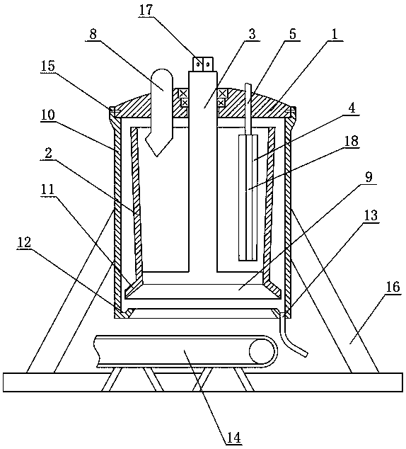
[0034] Such as Figure 1~Figure 3 As shown, an automatic vertical centrifugal dehydrator includes a top cover 1, a dehydration cylinder 2, a casing 10, a rotating shaft 3 and a scraper 4, the dehydration cylinder 2 and the casing 10 are located under the top cover 1, and the dehydration cylinder 2 is arranged on the casing 10 Inside, it is fixedly connected with the rotating shaft 3, the rotating shaft 3 is rotationally connected with the top cover 1, and the scraper 4 is arranged in the dehydration cylinder 2, and is rotationally connected with the top cover 1. A conveyer belt 14 is arranged at the bottom of the dehydration cylinder 2 , the top cover 1 and the shell 10 are connected through a connecting device 15 , and the connecting shell 10 is set on a bracket 16 . The connecting device 15 is a connecting plate evenly distributed on the joint of the top cover 1 and the casing 10 , one end is fixedly connected to the casing 10 , and the other end is bolted to the top cover 1...

Embodiment 2

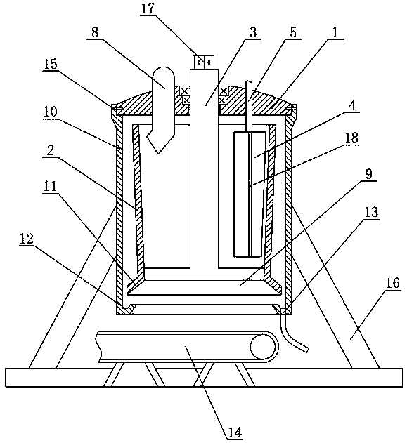
[0043] Such as Figure 4 As shown, in this embodiment, the top cover 1 is provided with two scrapers 4, and the centers of the two scrapers 4 are arranged symmetrically, and the center of symmetry is the rotating shaft 3, and the rotation directions of the scrapers 4 are also opposite. The two scrapers 4 rotate at the same time, and the dehydration barrel 2 is cleaned simultaneously, so that the dehydration barrel 2 rotates more stably when cleaning. Other parts in this embodiment are basically the same as those in Embodiment 1.


PUM


Abstract

The invention relates to the field of powder material dewatering equipment, in particular to an automatic vertical centrifugal dewatering machine. Continuous dewatering work of the vertical centrifugal dewatering machine can be achieved. The automatic vertical centrifugal dewatering machine comprises a dewatering cylinder, a shell, a top cover, a rotating shaft and a scraping plate; the dewateringcylinder and shell are arranged below the top cover, the dewatering cylinder is arranged in the shell and fixedly connected with the rotating shaft, the rotating shaft is rotatably connected with thecenter of the top cover, the scraping plate is arranged in the dewatering cylinder, and a control shaft is arranged at the top of the scraping plate, rotatably connected with the top cover, and connected with a driving device; the upper part and the lower part of the dewatering cylinder are open, the bottom of the shell is inwards bent to form a water receiving tank, a water draining opening is formed in the bottom of the water receiving tank, and a conveyor belt is arranged at the bottom of the dewatering cylinder; when the scraping plate rotates by different angles, the distances between the scraping plate and the inner wall of the dewatering cylinder are different, the dewatering cylinder has taper, and the top diameter of the dewatering cylinder is larger than the bottom diameter of the dewatering cylinder; a connecting shaft part is arranged at the top of the rotating shaft; and the shell and the top cover are detachably connected through a connecting device.

Description

technical field [0001] The invention relates to the field of powder material dehydration equipment, in particular to an automatic vertical centrifugal dehydrator. Background technique [0002] For some powdery materials in daily life, such as food or chemical products, it is necessary to dehydrate the liquid with high concentration and then dry it to obtain the final product. The most common way of dehydration is centrifugal dehydration, and centrifugal dehydration is divided into horizontal centrifugation and vertical centrifugation. Horizontal centrifugation can realize continuous work, but because the torque of each part of the dehydration cylinder is unbalanced, the speed of the centrifugal device is relatively slow, and the dehydration effect is poor. Vertical centrifugation can achieve high-speed centrifugation, but the material cannot be dehydrated continuously. It needs to stop after one dehydration, take out the material, clean the inner wall of the dehydration cyl...

Claims


Application Information

Patent Timeline
Patent Type & Authority Applications(China)
IPC IPC(8): F26B11/10F26B25/04F26B25/00F26B25/02
CPCF26B11/10F26B25/00F26B25/02F26B25/04
Inventor 李文博
Owner 李文博
Why Eureka
Try Eureka