Automatic veneer drying device

A drying device and veneer technology, which is applied in drying, drying machine, wood drying, etc., can solve the problems of large area occupied by drying sites, increased production costs, and large labor costs, and achieve fast and accurate veneer delivery, production Satisfied efficiency and effective drying rate

Pending Publication Date: 2020-12-15
山东利森智能装备有限公司
View PDF1 Cites 1 Cited by
  • Summary
  • Abstract
  • Description
  • Claims
  • Application Information

AI Technical Summary

Problems solved by technology

[0004] And the problem that existing this operating method exists is: one, need a large amount of labor force, and the veneer that separates by artificial is easy to produce tearing damage, causes it to become unqualified product and can't be used, affects its yield rate, causes waste; 2. The drying site covers a large area, and the drying effect and drying cycle are greatly affected by the weather. In case of rainy weather or weather changes, it is necessary to collect the dried veneer. The labor cost is relatively large, and the temperature is too high. Warped or curly; the drying site of one mu of land can only dry 3m3 veneer in a day when the weather is good, such as 25 degrees to 28 degrees; if the ambient temperature is too low or the humidity is too heavy, the number of days to dry Or extended, resulting in a significant reduction in veneer production capacity, resulting in increased production costs and low production efficiency
The defect of this technical solution is: the upper end of the veneer needs to be clamped for feeding, and the distance between the veneer needs to be controlled by a fixture, the device is complicated, it is difficult to position the soft and thin veneer, and the damage to the veneer is great. No automated collection scheme provided

Method used


Image

  • Automatic veneer drying device
  • Automatic veneer drying device
  • Automatic veneer drying device

Examples


Embodiment 1

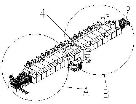
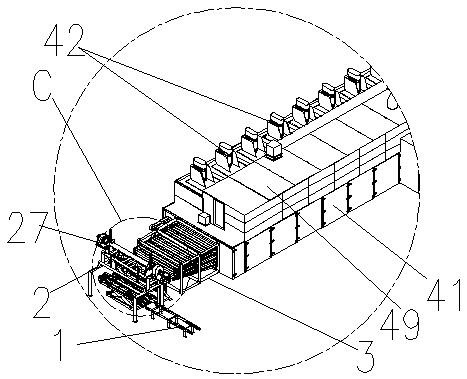
[0077] Example 1. Such as Figure 1-29 As shown, an automatic veneer drying device is characterized in that it includes: a feeding unit 1, a feeding unit 2, a transition guide frame 3, a drying unit 4, and a discharging unit 5;

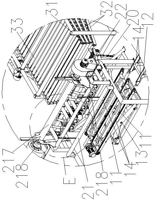
[0078] The drying unit 4 comprises a hot smoke system, a heat exchange system, a drying box 41, and several heat extraction fans 42; , in the right two ends, it is provided with the veneer inlet that links to each other with transition guide frame 3 near transition guide frame 3 end, is provided with the veneer outlet that links to each other with discharge unit 5 near discharge unit 5 end; Several horizontal drying layers 43, each horizontal drying layer 43 is provided with several horizontal drying layer longitudinal transmission rollers 44 with the top surface level, each horizontal drying layer longitudinal transmission roller 44 is connected with the horizontal drying layer longitudinal transmission roller driving motor 45 are connected; the ho...

Embodiment 2

[0107] Example 2. Such as Figure 21 As shown, the difference between this embodiment and Embodiment 1 is that no pallet lifting device is provided below the veneer conveyor belt 14 located in the frame body 11 of the feeding unit 1 of the feeding unit 1 .


PUM


Abstract

The invention discloses an automatic veneer drying device. The automatic veneer drying device comprises a feeding unit, a loading unit, a transition guide frame, a drying unit and a discharging unit,wherein the drying unit comprises a hot smoke system, a heat exchange system, a drying box and multiple heat extraction fans; the gap between the left end and the right end of the drying box is largerthan the gap between the front end and the back end of the drying box; the hot smoke system comprises a combustion furnace, a hot smoke pipe and a chimney; the transition guide frame comprises a transition guide frame body; frame plates as many as feed ends of horizontal drying layers of the drying unit are arranged on the transition guide frame body; the loading unit comprises a loading unit frame body, a guide plate frame arranged on the loading unit frame body, a suction module and a suction lifting adjusting module; the feeding unit is arranged below the suction module; and the discharging unit is connected with a veneer outlet of the drying unit. The drying device can absorb soft, light and thin veneers, quickly and accurately feeds the veneers into each horizontal drying layer of the drying unit for drying and automatic collection, and has the characteristics of high drying efficiency and continuous operation.

Description

technical field [0001] The invention relates to a drying device for use in the case of product drying. More specifically, the present invention relates to an automated veneer drying device used in the case of veneer processing. Background technique [0002] Wood veneer, commonly known as middle skin, is made of wet miscellaneous wood after sawing to a fixed length, and then turned by rotary cutting. Its main use is the main raw material for multi-finished boards, wood formwork, woodworking boards, and composite ecological boards. The market demand is large. [0003] After the product is processed, it has the characteristics of high water content, thinness, and easy tearing. Generally speaking, the current market demand for it is: 1300mm*800mm, thickness 0.6mm-2mm, and this kind of veneer is processed and turned. In order to ensure the effect and stability of turning, the usual practice is to perform processing operations when the segmented round wood has moisture, so the ve...

Claims


Application Information

Patent Timeline
Patent Type & Authority Applications(China)
IPC IPC(8): F26B15/12F26B5/04F26B21/00F26B25/00
CPCF26B5/04F26B15/122F26B21/002F26B25/003F26B2210/16
Inventor 冷金海
Owner 山东利森智能装备有限公司
Why Eureka
Try Eureka