Microwave assembly welding device

A technology of microwave components and welding devices, applied in auxiliary devices, welding equipment, auxiliary welding equipment, etc., can solve the problems of uneven pressure point pressure, poor welding air tightness, poor penetration rate, etc., and achieve good welding quality consistency , high welding flatness and high welding efficiency

Active Publication Date: 2017-01-04
SHANGHAI SPACEFLIGHT INST OF TT&C & TELECOMM
View PDF10 Cites 4 Cited by
  • Summary
  • Abstract
  • Description
  • Claims
  • Application Information

AI Technical Summary

Problems solved by technology

[0004] 1. When welding microwave substrates, some parts will warp due to uneven heating when microwave substrates are heated and welded. After heating, microwave substrates are warped and deformed during the welding process. The rear flatness is poor, and the welding quality is difficult to guarantee
[0005] 2. When the microwave substrate is pressure-welded, the force point of the microwave substrate is small and the force is uneven. When the pressure is large, it is easy to damage the surface pad or wiring of the microwave substrate, such as patent CN 203316963U microwave component substrate reflow soldering Elastic ballast device, uneven pressure point pressure during assembly, affecting product quality
[0006] 3. It takes a long time to heat the glass beads and connectors one by one. When ...

Method used


Image

  • Microwave assembly welding device
  • Microwave assembly welding device
  • Microwave assembly welding device

Examples


Embodiment Construction

[0038] In order to make the object, technical solution and advantages of the present invention clearer, various embodiments of the present invention will be described in detail below in conjunction with the accompanying drawings.

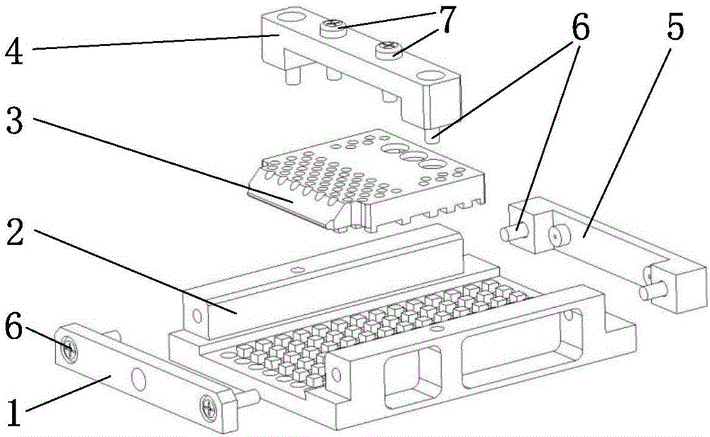
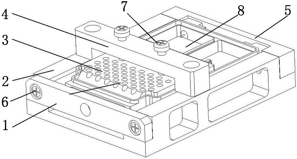
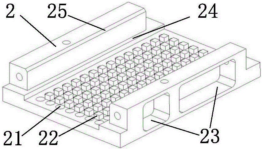
[0039] Please refer to figure 1 with figure 2 , a microwave assembly welding device, used for welding a microwave assembly 8 including a box body 81, a microwave substrate 83, a glass bead 84 and a connector 85, which includes a base 2, a left pressing block 1, a right pressing block 5, Upper pressing block 3 and beam 4;

[0040] The left pressing block 1 is fixedly connected with the base 2 for pressing the connector 85;

[0041] The right pressing block 5 is fixedly connected with the base 2 for pressing the glass beads 84;

[0042] The upper pressing block 3 is placed inside the box body 81 for pressing the microwave substrate 83;

[0043] The beam 4 is fixedly connected with the base 2 and is used for pressing the upper pressing block 3 . ...


PUM


Abstract

The invention discloses a microwave assembly welding device used for welding a microwave assembly comprising a box body, a microwave substrate, glass beads and a connector. The microwave assembly welding device comprises a base, a left pressing block, a right pressing block, an upper pressing block and a cross beam. The left pressing block is fixedly connected with the base and used for pressing the connector. The right pressing block is fixedly connected with the base and used for pressing the glass beads. The upper pressing block is put in the box and used for pressing the microwave substrate. The cross beam is fixedly connected with the base and used for pressing the upper pressing block. The base comprises a base bottom and guide pillars, wherein supporting bosses are arranged on the upper surface of the base bottom in an array mode, positioning faces flush with the upper surfaces of the supporting bosses are arranged on the two sides of the supporting bosses, the guide pillars are located on the positioning faces, and the inner sides of the guide pillars are of plane structures and are used for clamping the two sides of the microwave assembly. Pressurizing bosses arranged in an array mode and ventilation lightening holes which are adjacent to the pressurizing bosses and are arranged in an array mode are arranged on the lower surface of the upper pressing block. The microwave assembly welded with the microwave assembly welding device has the advantages that the welding flatness is high, the penetration rate and the welding efficiency are high, and the welding quality uniformity is good.

Description

technical field [0001] The invention relates to an electronic product welding device, in particular to a microwave component welding device used in the aerospace field. Background technique [0002] The microwave component is the basis of the active phased array radar antenna and the core component of the active phased array radar. The consistency of the welding quality of the microwave component directly affects the overall machine index of the radar. An active phased array radar needs tens of hundreds of microwave components at least, and tens of thousands of microwave components at most. The welding of box body, microwave substrate, glass beads and connectors of microwave components is the basis of microwave component welding, and its welding quality directly affects the performance of microwave components. [0003] At present, the welding of microwave component boxes, microwave substrates, glass beads, and connectors is mainly carried out in the following steps. First, ...

Claims


Application Information

Patent Timeline
IPC IPC(8): B23K37/04
CPCB23K37/0443
Inventor 赵涌曹向荣吴毓颖罗燕王立春
Owner SHANGHAI SPACEFLIGHT INST OF TT&C & TELECOMM
Why Eureka
Try Eureka