Sand blasting machine and method for removing plastic-product rough edge and gas marks through sand blasting machine

A sandblasting machine and plastic technology, applied in the direction of abrasive jetting machine tools, used abrasive processing devices, abrasives, etc., can solve the problems of increased labor costs, low efficiency of manual processing, and high risk of work-related injuries, so as to reduce injuries risk, solve burrs and air marks, and save labor costs

Active Publication Date: 2017-01-04
周选保
View PDF7 Cites 4 Cited by
  • Summary
  • Abstract
  • Description
  • Claims
  • Application Information

AI Technical Summary

Problems solved by technology

The existing technology to solve the problems of burrs and air marks of injection molded parts is mainly to use tools such as blades to solve them manually. On the one hand, this method increases labor costs, and the efficiency of manual processing is low. At the same time, some smaller plastic products such as The quality of computer keyboard keys cannot be guaranteed after the raw edges are processed, and the quality cannot meet the requirements of manufacturers and consumers
In addition, manual processing is adopted, and the operator is easily scratched by the blade, and the risk of work-related injury is high

Method used


Image

  • Sand blasting machine and method for removing plastic-product rough edge and gas marks through sand blasting machine
  • Sand blasting machine and method for removing plastic-product rough edge and gas marks through sand blasting machine
  • Sand blasting machine and method for removing plastic-product rough edge and gas marks through sand blasting machine

Examples


Embodiment Construction

[0028] The specific implementation manners of the present invention will be further described in detail below in conjunction with the accompanying drawings and embodiments. The following examples are used to illustrate the present invention, but are not intended to limit the scope of the present invention.

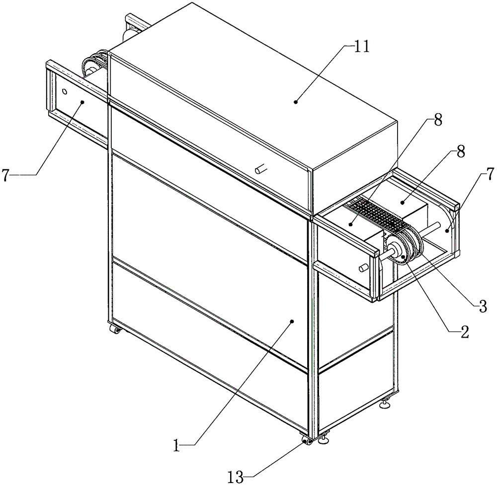
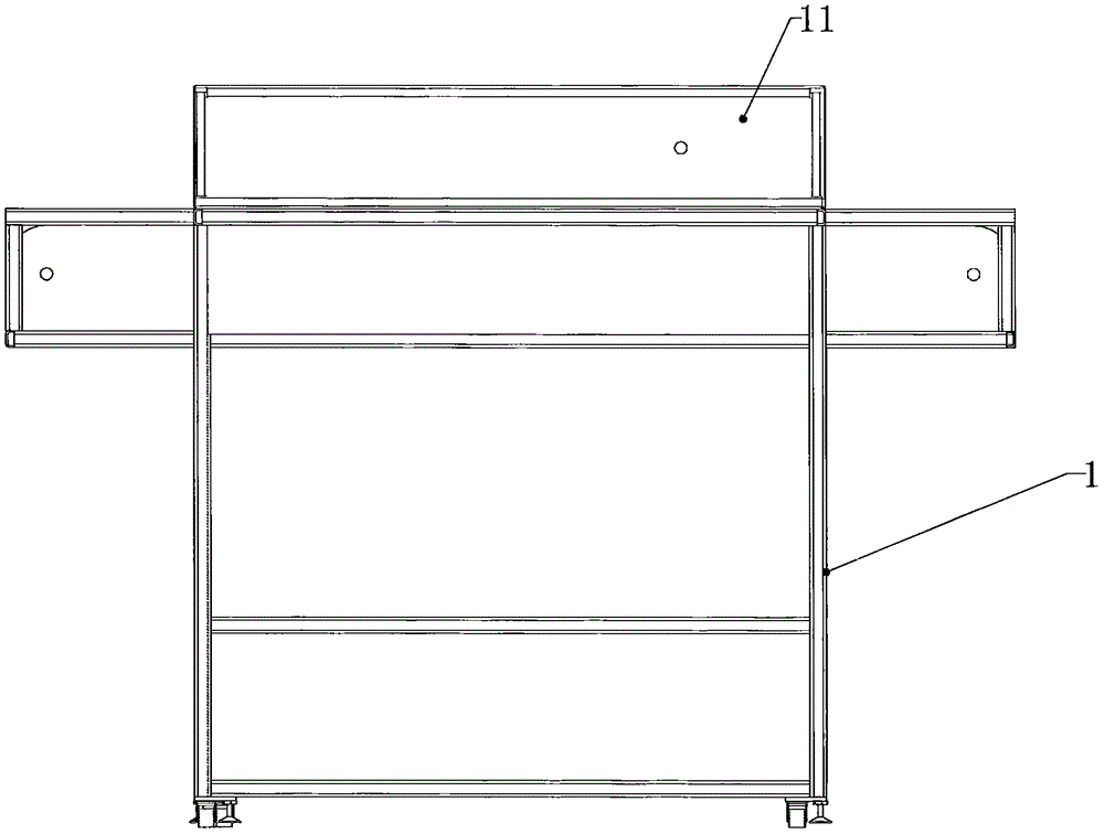
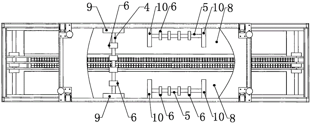
[0029] see figure 1 and figure 2 , a kind of blasting machine of a preferred embodiment of the present invention, comprises frame 1, conveying device and blasting device, and conveying device comprises pulley 2 and conveyer belt 3, and the number of pulley is two, and two The pulleys are respectively arranged at the left and right ends of the frame, the conveyor belt is arranged on the pulleys and the conveyor belt is driven by the pulleys, the sandblasting device includes a first rotating shaft 4 and two second rotating shafts 5, the first rotating shaft and the conveying direction of the conveyor belt are basically Vertical, the second rotating shaft is basically para...


PUM


Abstract

The invention relates to a sand blasting machine. The sand blasting machine comprises a machine frame, a conveying device and a sand blasting device. The conveying device comprises belt wheels and a conveying belt; the two belt wheels are arranged at the left end and the right end of the machine frame respectively, the conveying belt is arranged on the belt wheels and driven by the belt wheels. The sand blasting device comprises a first rotating shaft and second rotating shafts; the first rotating shaft is basically perpendicular to the conveying direction of the conveying belt, the second rotating shafts are basically parallel to the conveying direction of the conveying belt, the two second rotating shafts are located on the front side and the back side of the conveying belt respectively, and blasting heads for blasting sand are arranged on the first rotating shaft and the second rotating shafts respectively and located on the conveying belt. According to the sand blasting machine, as the blasting heads are arranged, plastic-product rough edge and gas marks can be effectively removed, the processing efficiency is high, and the industrial injury risk is low. The invention also relates to a method for removing plastic-product rough edge and gas marks through the sand blasting machine, and operators can effectively remove plastic-product rough selvedges and gas marks with the method.

Description

technical field [0001] The invention relates to an abrasive jetting device, in particular to a sandblasting machine and a method for removing burrs and air marks of plastic products by using the sandblasting machine. Background technique [0002] With the development of society and the progress of science and technology, manufacturers and consumers have higher and higher requirements for injection molded parts, but in general, injection molded parts produced by machines will have more or less burrs of 0.03-0.05 mm, so, In order to achieve the requirement of zero burrs, the injection molded parts produced must undergo secondary processing. The existing technology to solve the problems of burrs and air marks of injection molded parts is mainly to use tools such as blades to solve them manually. On the one hand, this method increases labor costs, and the efficiency of manual processing is low. At the same time, some smaller plastic products such as The quality of computer keyb...

Claims


Application Information

Patent Timeline
Patent Type & Authority Applications(China)
IPC IPC(8): B24C3/08B24C9/00B24C1/08
CPCB24C1/083B24C3/083B24C3/085B24C9/00B24C9/006
Inventor 周选保陆蓉谭贱华
Owner 周选保
Why Eureka
Try Eureka