Automatic centring and clamping mechanism

A clamping mechanism and automatic centering technology, applied in the direction of workpiece clamping device, auxiliary device, auxiliary welding equipment, etc., can solve the problems of low work efficiency and high labor intensity

Active Publication Date: 2017-01-04
XIAN AEROSPACEMOTOR MACHINE FACTORY
View PDF6 Cites 11 Cited by
  • Summary
  • Abstract
  • Description
  • Claims
  • Application Information

AI Technical Summary

Problems solved by technology

[0003] In order to overcome the shortcomings of low work efficiency and high labor intensity in the prior art, the present invention proposes an automatic centering clamping mechanism

Method used


Image

  • Automatic centring and clamping mechanism
  • Automatic centring and clamping mechanism
  • Automatic centring and clamping mechanism

Examples


Embodiment Construction

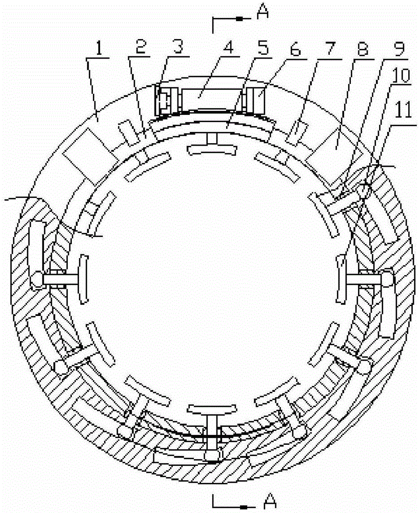
[0019] This embodiment is an automatic centering clamping mechanism, which can realize the automatic rounding of cylindrical and shell parts during the clamping process.

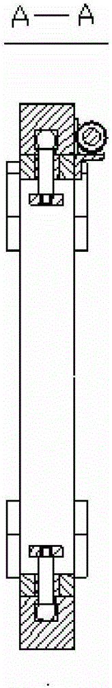
[0020] This embodiment includes an outer ring body 1, an inner ring body 2, a hand wheel 3, a worm 4, a worm gear body 5, a bearing seat 6, a guide sleeve 9, a limiter 7, an axial stopper 8 and a telescopic body. The telescopic body includes a telescopic shaft 10 and a clamping block 11 . Wherein, the outer ring body 1 is sleeved on the outer peripheral surface of the inner ring body 2, and there is a clearance fit between the two. The ball ends of the telescopic shafts 10 in the plurality of telescopic bodies pass through the guide holes on the circumference of the inner ring body 2 and are loaded into each chute on the inner surface of the outer ring body 1 . The worm gear body 5 is fixed on the end face of the inner ring body 2; the worm 4 is fixed on the end face of the outer ring body 1 through the bea...


PUM


Abstract

The invention discloses an automatic centring and clamping mechanism. An outer ring body is arranged on the surface of the outer circumference of an inner ring body in a sleeving manner, and the outer ring body and the inner ring body are in clearance fit. The ball head ends of telescopic shafts in a plurality of telescopic bodies penetrate guide holes in the circumference of the inner ring body and then are mounted in sliding grooves located in the inner circle surface of the outer ring body. A worm gear body is fixed to the end face of the inner ring body. A worm is fixed to the end face of the outer ring body through a bearing pedestal and engaged with the worm gear body, and therefore the outer ring body and the inner ring body generate relative rotation. The number of the guide holes in the surface of the outer circumference of the inner ring body, the number of the sliding grooves in the surface of the inner circumference of the outer ring body and the number of the telescopic shafts are the same. According to the automatic centring and clamping mechanism, in the clamping process, all clamping blocks stretch out and retract back at the same time through telescopic bolts, and the clamping blocks are rounded at the same time in the clamping process; and in the whole implementation process, no machine tool is needed, operation is easy and convenient, efficiency is high, and the high application and popularization value is achieved.

Description

technical field [0001] The invention relates to the field of mechanical manufacturing, in particular to an automatic centering clamping mechanism used in the manufacture of aerospace solid rocket motor metal shells, pressure vessels and thin-walled cylindrical parts in other fields Background technique [0002] In the manufacture of aerospace rocket engine metal shells and various pressure vessels, they are basically rolled and welded by sheet metal, or processed and welded by spinning formed thin-walled tube sections. Both the spin-formed tube section and the roll-welded thin-walled tube section have large deformations. In the processing of the cylinder section, the assembly welding of the cylinder section and the cylinder section, and the processing of forming the shell, the external clamping mechanism is required to correct the circle of the cylinder section or the inner support to support the circle before processing and welding, and for diameters less than 200mm and sma...

Claims


Application Information

Patent Timeline
Patent Type & Authority Applications(China)
IPC IPC(8): B25B11/00B23K37/053
CPCB23K37/0533B25B11/00
Inventor 王浩刚何方王惠傅毅恺任长洁张迎
Owner XIAN AEROSPACEMOTOR MACHINE FACTORY
Why Eureka
Try Eureka