
Vertebral column joint assembly of intelligent simulation robot

A technology of intelligent robot and spine, which is applied in the field of robotics, can solve the problems of low simulation degree, clumsy bulkiness, inflexibility of spine joints, etc., and achieve the effect of light weight and high simulation degree

Active Publication Date: 2017-01-04
河南豫科电气有限公司
View PDF5 Cites 14 Cited by
  • Summary
  • Abstract
  • Description
  • Claims
  • Application Information

AI Technical Summary

Problems solved by technology

[0003] The purpose of the present invention is to overcome the problems that the existing robotic spinal joints cannot bend left and right like a real human spinal joint, bend forward and backward, turn around flexibly, and its structure is far from that of a real human spinal joint. Provide a spinal joint assembly of a simulated intelligent robot that corresponds to the size of the spinal joint of a real person, is flexible and has a high degree of simulation

Method used


Image

  • Vertebral column joint assembly of intelligent simulation robot
  • Vertebral column joint assembly of intelligent simulation robot
  • Vertebral column joint assembly of intelligent simulation robot

Examples


Embodiment Construction

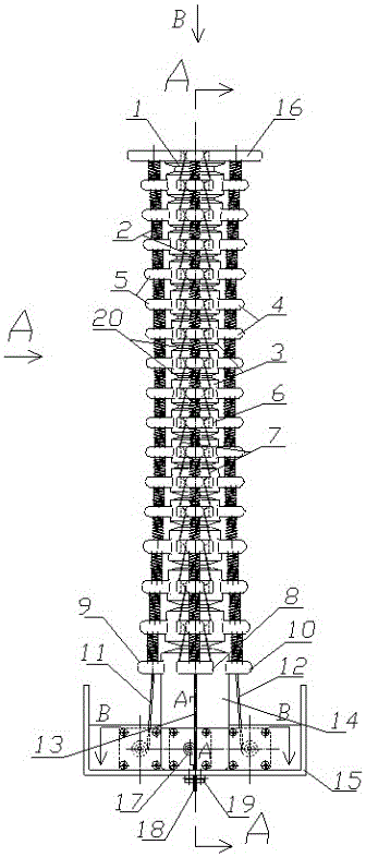
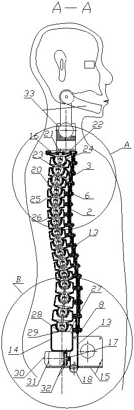
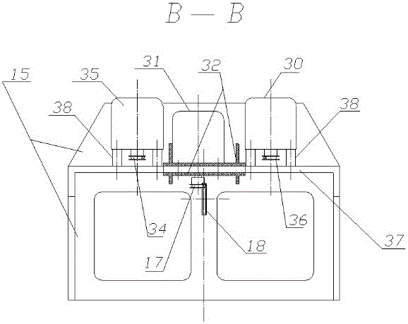
[0033]As can be seen clearly from each figure of specific embodiment, the present invention comprises coccyx 14, apical vertebra 1, fifteen middle vertebra 3, is positioned on hip joint assembly (another case application) pedestal 15 middle dividing plate 37 Left and right side bending over motor 35,30, front and rear bending over motor 31, the left and right turning waist motor 27 that is positioned in the tail vertebra 14, one end is positioned on the tail vertebra 14 inner turning waist motor output shaft 29 and passes through the middle of fifteen The other end of the inner center of the vertebra 3 is positioned on the universal joint chain on the top vertebra 1. The tail vertebra 14 is a hollow barrel-shaped structure and the waist-turning motor 27 is positioned inside it. The upper part is provided with a concave spherical surface 28 that is transparent up and down. , the output shaft 29 of the waist-turning motor passes upwards through the hole below the concave spherica...


PUM


Abstract

The invention relates to a vertebral column joint assembly of an intelligent simulation robot. The vertebral column joint assembly is characterized in that the whole vertebral column joint assembly comprises a caudal vertebra, a top vertebra, multiple middle vertebrae, a left-side waist turning motor, a right-side stooping motor, a front-and-back stooping motor, a left-and-right stooping motor and a universal joint chain, wherein the left-side stooping motor and the right-side stooping motor are positioned on a middle partition plate of a hip joint assembly base frame, the left-and-right waist turning motor is positioned in the caudal vertebra, one end of the universal joint chain is positioned on an output shaft of the waist turning motor arranged in the caudal vertebra and penetrates through the middle vertebrae, and the other end of the universal joint chain is positioned on the top vertebra; the waist turning motor is arranged in the caudal vertebra, the upper portion of the caudal vertebra is provided with an inwards-concave spherical surface, the lower portion of the caudal vertebra is provided with a grooved clamp plate, the outer upper portion of the caudal vertebra is provided with a left wing, a right wing and a front wing which are each provided with a line passing hole, and compression springs are arranged in the line passing holes formed in the left wings, the right wings and the front wings of all the vertebra joints. The vertebral column joint assembly has the advantages that the stooping actions and the waist turning actions have no difference with those of a real person, the structure is close to that of the real person, and therefore the vertebral column joint assembly is high in simulation degree and flexible; the vertebral column joint assembly is mainly made from aluminum alloy or magnalium alloy or a carbonic acid fiber material or the like, and therefore the weight is low.

Description

technical field [0001] The invention relates to the field of robots, in particular to a spine joint assembly for simulating an intelligent robot. Background technique [0002] In the field of robotics in the prior art, there are many structures related to spinal joints, but there are common problems: they cannot bend left and right like the real spinal joints, and they can bend back and forth flexibly. Big size. This makes it impossible to correspond to the size of the real person's spinal joints, let alone the simulated human spinal joints. How to overcome the deficiencies existing in the prior art, so that the size of the robot's spinal joints corresponds to the size of the real person's spinal joints, and at the same time, to provide a spine joint assembly for simulating intelligent robots, which has become the main focus of the present invention research topic. Contents of the invention [0003] The purpose of the present invention is to overcome the problems that t...

Claims


Application Information

Patent Timeline
IPC IPC(8): B25J17/00
CPCB25J17/00
Inventor 李德福
Owner 河南豫科电气有限公司
Features
  • Generate Ideas
  • Intellectual Property
  • Life Sciences
  • Materials
  • Tech Scout
  • Unparalleled Data Quality
  • Higher Quality Content
  • 60% Fewer Hallucinations
Learn More