Device for vertically cutting concrete pole in segmented mode

A cutting device and concrete technology, applied in the direction of stone processing tools, work accessories, manufacturing tools, etc., can solve the problems of high labor intensity of workers, inability to ensure the direction of the poles toppling, and the length of the poles, etc., to improve the safety of cutting. Effect

Active Publication Date: 2017-01-04
SHANGHE COUNTY POWER SUPPLY CO STATE GRID SHANDONG ELECTRIC POWER CO +1
View PDF5 Cites 3 Cited by
  • Summary
  • Abstract
  • Description
  • Claims
  • Application Information

AI Technical Summary

Problems solved by technology

In some power system reconstruction projects, it is necessary to remove some unnecessary concrete poles. The existing concrete poles are generally removed manually. The method is to first smash the concrete on the bottom surface of the poles with a sledgehammer, Then the steel bars in the electric poles are cut off by gas cutting, which has great safety problems, and at the same time, the labor intensity of workers is relatively large; the Chinese utility model patent whose authorization announcement number is CN205272347U discloses a concrete electric pole cutter, which The cutter includes walking wheels, a base, a control box, a water tank, a power box, a drive motor and a cutting saw blade. Although the cutter realizes the way of cutting the electric pole with instruments, it cannot guarantee that the electric pole will fall during the cutting process. direction, there is a big potential safety hazard, and the length of the cut pole is still long, making it inconvenient to transport the pole without a large transport vehicle

Method used


Image

  • Device for vertically cutting concrete pole in segmented mode
  • Device for vertically cutting concrete pole in segmented mode
  • Device for vertically cutting concrete pole in segmented mode

Examples


Embodiment Construction

[0022] The following will combine specific embodiments and appendices Figure 1-5 The technical solutions in the embodiments of the present invention are described clearly and completely. Obviously, the described embodiments are only a part of the preferred embodiments of the present invention, rather than all the embodiments. Those skilled in the art can make similar modifications without departing from the connotation of the present invention. Therefore, the present invention is not limited by the specific embodiments disclosed below.

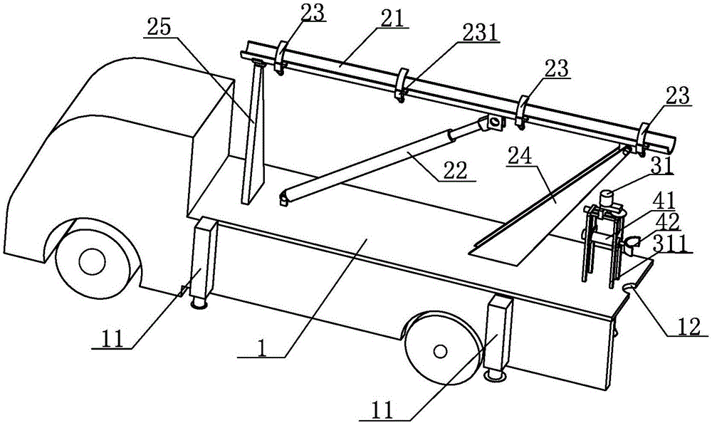
[0023] The invention provides a device for vertically segmented cutting concrete poles (such as figure 1 (Shown), including a vehicle-mounted chassis 1, an embracing device, and a cutting mechanism. On both sides of the vehicle-mounted chassis 1, there are telescopic hydraulic legs 11 opposite to each other. The vehicle-mounted chassis 1 can travel freely, and the hydraulic legs 11 are the same as the existing ones. The design principle of the o...


PUM


Abstract

The invention provides a device for vertically cutting a concrete pole in a segmented mode. The device comprises a vehicle-mounted chassis, a surrounding device and a cutting mechanism; telescopic hydraulic support legs are oppositely arranged on the two sides of the vehicle-mounted chassis, the surrounding device comprises an arc-shaped surrounding plate, a first hydraulic oil cylinder, a rotating support frame and a flatwise placing support frame, the cutting mechanism comprises an upper cutting device and a lower cutting device, the upper cutting device and the lower cutting device each comprises a cutting assembly, and each cutting assembly comprises a driving motor, a cutting blade and a screw transmission mechanism, wherein the driving motor adopts belt transmission to drive the cutting blade, and the driving motor and the cutting blade are both fixedly arranged on a mobile sliding block of the screw transmission mechanism. According to the device, the arc-shaped surrounding plate can vertically fix the waste concrete pole, the pole cannot be tilted after the bottom end of the pole is cut off, and therefore accidents are avoided; the cutting mechanism can achieve segmented cutting on the pole along with continuous downward movement of the pole in the arc-shaped surrounding plate, and the cut pole is beneficial for transportation.

Description

Technical field [0001] The invention relates to a cutting tool, in particular to a vertical section cutting concrete pole device. Background technique [0002] Concrete poles are commonly used in rural power construction projects in my country. Concrete poles are generally made of concrete and steel bars, which have a strong supporting role. In some power system renovation projects, it is necessary to remove some unused concrete poles. The existing concrete poles are generally demolished manually. The method is to first use a sledgehammer to drop the concrete on the bottom surface of the pole. Then use gas cutting to cut the steel bars in the pole. This method has a big safety problem. At the same time, the labor intensity of the workers is relatively high. The Chinese utility model patent with the authorization announcement number CN205272347U discloses a concrete pole cutter. The cutter includes a walking wheel, a base, a control box, a water tank, a power box, a drive motor, ...

Claims


Application Information

Patent Timeline
IPC IPC(8): B28D1/24B28D7/00B28D7/04
CPCB28D1/24B28D7/00B28D7/04
Inventor 翟伟王辉
Owner SHANGHE COUNTY POWER SUPPLY CO STATE GRID SHANDONG ELECTRIC POWER CO
Why Eureka
Try Eureka