
Method for changing and transferring catenary rods

A catenary and frame bridge technology, applied in the direction of overhead lines, building types, buildings, etc., can solve the problems of large changes in catenary poles, high construction costs, high risks, etc., and achieve small impact, simple construction, and good stability Effect

Active Publication Date: 2017-01-04
CHINA RAILWAY SIXTH GRP TIANJIN RAILWAY CONSTR +1
View PDF8 Cites 2 Cited by
  • Summary
  • Abstract
  • Description
  • Claims
  • Application Information

AI Technical Summary

Problems solved by technology

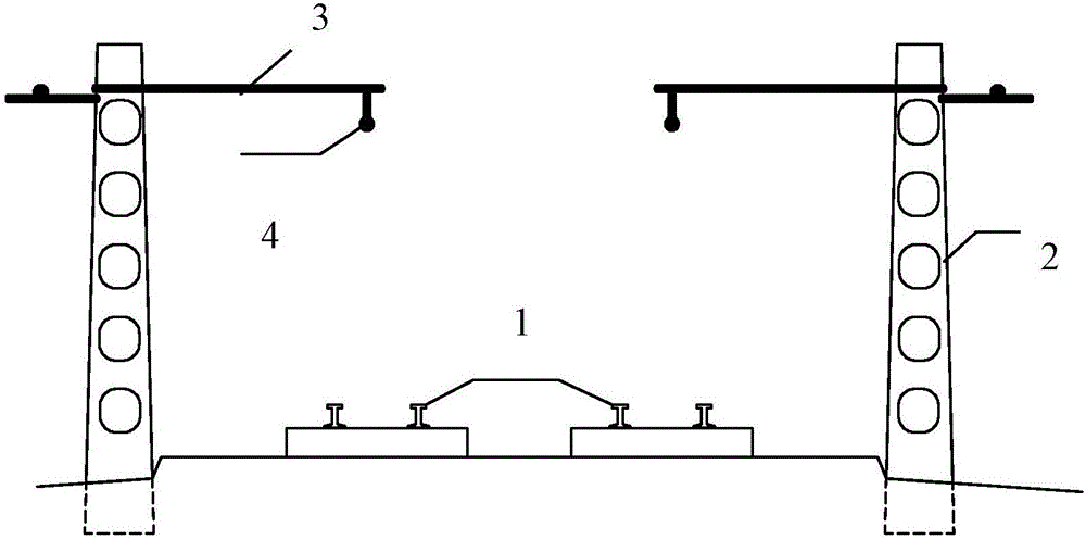
The disadvantage of the former construction method is that it is more cumbersome. First, the original catenary pole 2 needs to be moved and then restored, and the construction cost is relatively high.
The disadvantage of the latter construction method is that it is greatly affected by the jacking of the frame bridge. If the subgrade collapses or the frame bridge "heads up" or "heads up", the catenary poles will change greatly, so the risk is also greater

Method used


Image

  • Method for changing and transferring catenary rods
  • Method for changing and transferring catenary rods
  • Method for changing and transferring catenary rods

Examples


Embodiment Construction

[0023] The catenary pole modification method provided by the present invention will be described in detail below in conjunction with the accompanying drawings and specific embodiments. The same reference numerals are used for the same components as in the prior art.

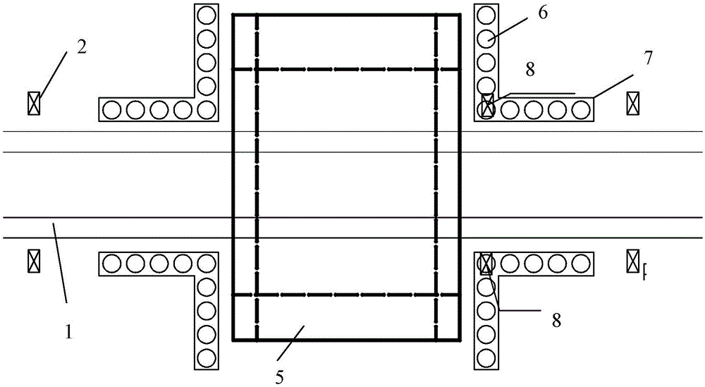
[0024] like image 3 — Image 6 As shown, the method for changing catenary rods provided by the invention includes the following steps carried out in order:

[0025] 1) Before the frame bridge 5 is jacked, a set of L-shaped reinforced concrete protection piles 6 and a reinforced concrete crown beam 7 at the top of the group of protection piles 6 are respectively installed on the railway subgrade on both sides of the front and rear ends of the frame bridge 5 to be installed. For railway subgrade protection, in the process of setting up protective piles 6 and crown beams 7, multiple screws and bolts are pre-embedded on the top of the crown beam 7 at the corner on one side, and the steel truss is softly spanned ac...


PUM


Abstract

The invention relates to a method for changing and transferring catenary rods. The method comprises the following steps of before a frame bridge is jacked, planting lower end parts of steel truss headspan suspension catenary rods into the corners of a top beam; temporarily connecting a guy wire to the tops of the two steel truss headspan suspension catenary rods corresponding to two sides of a railway line; transferring a catenary high-voltage line located on the frame bridge to the guy wire and disassembling the catenary rods; 4) recovering the operation of the railway line, and performing the jacking of the frame bridge by a conventional jacking method; disassembling the steel truss headspan suspension catenary rods from protecting piles and the top beam, hoisting the disassembled steel truss headspan suspension catenary rods to the frame bridge, and assembling the lower ends of the steel truss headspan suspension catenary rods to an anchoring bracket base together; and finally mounting supporting rods on the upper ends of the steel truss headspan suspension catenary rods and arranging the catenary high-voltage line on the supporting rods. The method disclosed by the invention has the effects that the stability is good; the construction is simple and convenient; the complexity and the danger of changing and transferring the catenary rods can be reduced; the influence on the normal operation of a railway can be reduced to minimum, and the cost is reduced; and the problem that the frame bridge in a long span cannot cross the railway is solved, and the technology is advanced.

Description

technical field [0001] The invention belongs to the technical field of railway bridge and culvert construction, in particular to a catenary pole modification method for a jacking area of ​​a railway frame bridge passing under it. Background technique [0002] With the continuous development of urban construction, the number of municipal roads crossing railways is increasing, and the planning width is increasing. At present, the railway tunnel is mainly used to cross the railway. The railway tunnel is mainly composed of a frame bridge and approach roads located at the front and rear ends of the frame bridge. The frame bridge is mostly set under the railway by jacking. figure 1 It is a schematic diagram of the planar structure of an electrified railway in the prior art. figure 2 It is a schematic cross-sectional view of an electrified railway in the prior art. like figure 1 , figure 2 As shown, a plurality of catenary poles 2 are arranged at intervals on both sides of th...

Claims


Application Information

Patent Timeline
Patent Type & Authority Applications(China)
IPC IPC(8): B60M1/28E04H12/22
CPCB60M1/28E04H12/2284
Inventor 于奇建陈巳龙刘伟李少鹏黄亚洲李强梁波
Owner CHINA RAILWAY SIXTH GRP TIANJIN RAILWAY CONSTR
Learn More