Remotely-operated submersible and remotely-operated submersible system
A technology for remote-controlled submersibles and submersibles, which is used in transportation and packaging, underwater operation equipment, ships, etc., and can solve problems such as no solution, limited detection range of underwater submersibles, and impact on the working efficiency of underwater submersibles. , to achieve the effect of extending the working range and increasing the signal transmission distance
- Summary
- Abstract
- Description
- Claims
- Application Information
AI Technical Summary
Problems solved by technology
Method used
Image

Examples
Embodiment 1
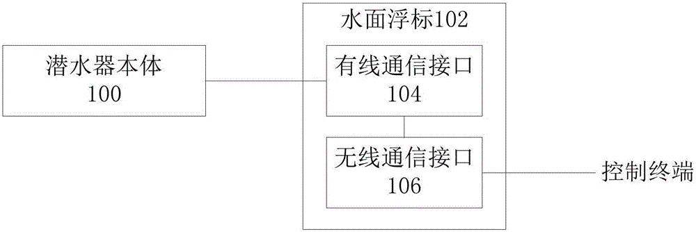
[0031] see figure 1 A schematic diagram of the structure of a remotely controlled submersible is shown. The ROV includes a submersible body 100 and a surface buoy 102;
[0032] The above-mentioned surface buoy 102 includes a wired communication interface 104 and a wireless communication interface 106, wherein the wired communication interface 104 is connected to the submersible body 100 through a cable; Terminal communication, so that the surface buoy 102 transmits the signal between the submersible body 100 and the control terminal, so that the control terminal can wirelessly control the submersible body;
[0033] The submersible body 100 collects data according to the control signal sent by the control terminal, and sends the collected data to the control terminal through the surface buoy 102 . The data collected by the submersible body includes image data, video data, speed, distance, temperature or pressure and other relevant survey data.
[0034] Specifically, the abov...
Embodiment 2
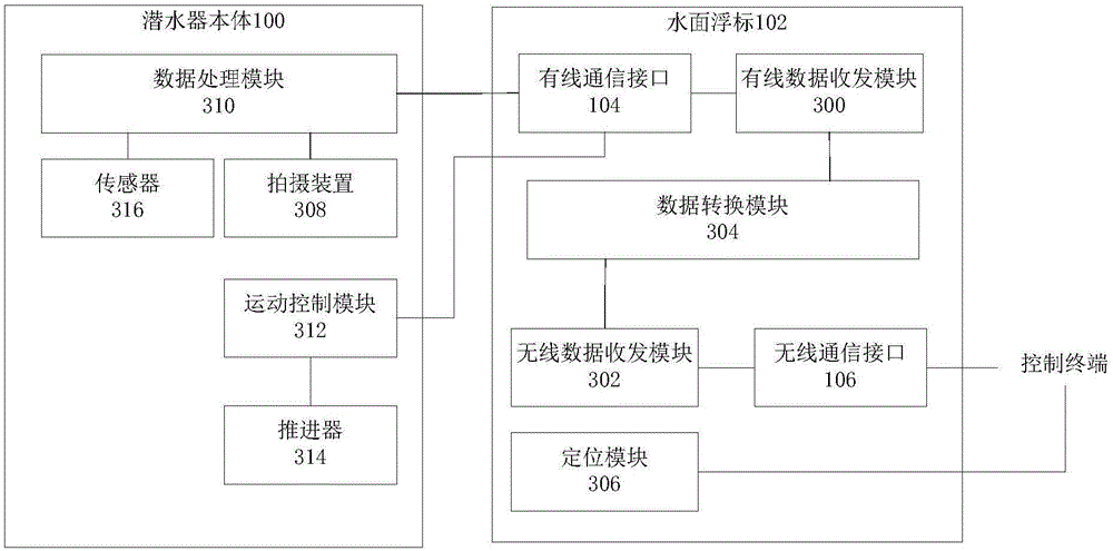
[0037] For a detailed description of the above ROVs, see figure 2 The schematic diagram of a specific structure of a remotely controlled submersible is shown; considering that the above-mentioned surface buoy needs to receive wired signals and wireless signals at the same time, and needs to convert the wired signal and wireless signal, the above-mentioned surface buoy also includes a wired data transceiver module 300, a wireless Data transceiver module 302 and data conversion module 304; The wired data transceiver module 300 transmits the wired signal of the submersible body through the wired communication interface; the wireless data transceiver module 302 transmits the wireless signal of the control terminal through the wireless communication interface; the data conversion module 304 It is used to convert between wired signals and wireless signals. Through the above method, the surface buoy can transmit, receive and convert wireless signals and wired signals, and then reali...
Embodiment 3
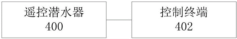
[0044] Corresponding to the embodiment of the above-mentioned remote control vehicle, the embodiment of the present invention provides a remote control vehicle system, see image 3 Shown is a schematic structural diagram of a remote-controlled vehicle system; the system includes the above-mentioned remotely operated vehicle 400, and also includes a control terminal 402; the control terminal 402 sends control signals to the submersible body through the surface buoy under the user's operation.
[0045] Specifically, the above-mentioned control terminal 402 may be a smart terminal, such as a mobile phone, a computer, a tablet computer, etc.; the control terminal may also be a remote controller, or the like.
[0046] A remotely operated vehicle system provided by an embodiment of the present invention includes a remotely operated vehicle and a control terminal; the remotely operated vehicle comprises a submersible body and a surface buoy; the wired communication interface of the su...
PUM
 Abstract
Description
Claims
Application Information
 - R&D
- Intellectual Property
- Life Sciences
- Materials
- Tech Scout
- Unparalleled Data Quality
- Higher Quality Content
- 60% Fewer Hallucinations
Browse by: Latest US Patents, China's latest patents, Technical Efficacy Thesaurus, Application Domain, Technology Topic, Popular Technical Reports.
© 2025 PatSnap. All rights reserved.Legal|Privacy policy|Modern Slavery Act Transparency Statement|Sitemap|About US| Contact US: help@patsnap.com