Electric control lifting device used for scanning bed

A lifting device and scanning bed technology, which is applied in the direction of lifting device, lifting frame, lifting equipment safety device, etc., can solve the pain of increasing the patient's body's multiple movements, the lack of stability of the push rod lifting, and the hardware damage of the scanning bed, etc. problems, to achieve the effect of strong design practicability, novel design and labor saving

Inactive Publication Date: 2017-01-04
孙传金
View PDF0 Cites 5 Cited by
  • Summary
  • Abstract
  • Description
  • Claims
  • Application Information

AI Technical Summary

Problems solved by technology

However, it is often encountered that the subject to be scanned has limited mobility, serious illness, and short stature, and cannot be placed on the scanning bed by itself. The pain of moving, the risk of radiation exposure to the patient's family members in the testing room, and reduces the efficiency of diagnosis and treatment
The lifting function of the MRI scanning table usually uses the screw nut pair to connect the lower end of the hinge swing rod, which drives the hinge to change the angle, and then raises or lowers the height of the scanning table. Tripping occurs, causing the scanning table to drop suddenly, increasing the risk of patient injury
In addition, the push rod can also be used to vertically push the scanning table to complete the lifting action, but the lifting of the push rod lacks stability, and due to the self-weight of the MRI scanning bed board and its large bearing capacity, the push rod needs to have high strength, which increases cost
[0003] In addition, in the ordinary MRI scanning table lifting control mechanism, relying on a single switch, single contact, and single contact to control the travel range of the mechanical movement, when the travel distance reaches the limit state, the switch contacts the contact and the movement stops Misoperation and other factors induce overtravel conditions, resulting in injury to patients or hardware damage on the scanning table

Method used


Image

  • Electric control lifting device used for scanning bed
  • Electric control lifting device used for scanning bed

Examples


Embodiment Construction

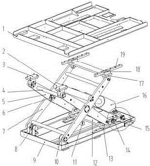
[0018] refer to Figure 1-2 As shown, the electronically controlled lifting device for the scanning bed includes a support plate 1, a base 9, and a lifting mechanism. The base is provided with a lifting mechanism for lifting the support plate. The lifting mechanism includes a hinge device, a sliding device, and a The hinge device realizes the driving mechanism of the lifting action. The hinge device includes an outer swing rod 7 and an inner swing rod 5. The above two swing rods are connected through the hinge shaft 6 in the middle. The sliding device includes an upper sliding device and a lower sliding device. The lower end of the outer swing rod is hinged on the base through the bearing seat 10, the upper end of the outer swing rod is slidably connected with the support plate through the upper sliding device, the upper end of the inner swing rod is hinged with the support plate through the bearing seat 3, and the lower end of the inner swing rod passes through The lower sli...


PUM


Abstract

The invention discloses an electric control lifting device used for a scanning bed. The electric control lifting device comprises a supporting plate, a base and a lifting mechanism. The base is provided with the lifting mechanism used for lifting the supporting plate. The lifting mechanism comprises a hinge device, a sliding device and a drive mechanism enabling the hinge device to achieve the lifting action. The hinge device comprises an outer swing rod and an inner swing rod. The above two swing rods are hinged to each other at the middle portion through a hinge shaft. The sliding device comprises an upper sliding device body and a lower sliding device body, wherein the upper end of the outer swing rod is connected with the supporting plate through the upper sliding device body in a sliding manner, and the lower end of the inner swing rod is connected with the base through the lower sliding device body in a sliding manner. The lower end of the drive mechanism is hinged to the base, and the upper end of the drive mechanism is hinged to a swing rod supporting frame transversely arranged in the middle of the outer swing rod. According to the electric control lifting device used for the scanning bed, the lifting, moving and positioning actions of the scanning bed can be accurately and stably completed. In addition, the automatic lifting mechanism has a stroke control double protection function, and double protection on the lifting stroke limiting position can be achieved respectively.

Description

technical field [0001] The invention relates to a supporting device for a scanning bed, in particular to an electronically controlled lifting device for a scanning bed. Background technique [0002] The electronically controlled lifting mechanism of the MRI scanning table is the matching mechanism of the MRI scanning table. The MRI scanning area is usually fixed and cannot be moved up and down at will, and the height of the scanning table must meet the detection distance requirements. The patient to be scanned lies flat on the scanning bed, and the patient is sent into the scanning area by the feeding system. However, it is often encountered that the subject to be scanned has limited mobility, serious illness, and short stature, and cannot be placed on the scanning bed by itself. The pain of moving, and the risk of radiation exposure to the patient's family members in the testing room, and reduces the efficiency of diagnosis and treatment. The lifting function of the MRI ...

Claims


Application Information

Patent Timeline
Patent Type & Authority Applications(China)
IPC IPC(8): B66F7/06B66F7/28B66F17/00A61B5/055
CPCA61B5/055B66F7/065B66F7/28B66F17/00
Inventor 孙传金
Owner 孙传金
Why Eureka
Try Eureka