A slag drainage device for slag wool and its application method

A technology of slag wool and slag, which is applied in the field of metallurgical slag, can solve the problems of inability to realize online heating and long-distance transportation of slag, adverse effects of the overall process layout scheme, and reduce the ratio of sensible heat utilization of slag, achieving obvious economical Benefits and promotional use value, obvious economic benefits and environmental benefits, long service life

Active Publication Date: 2019-01-08
ANGANG STEEL CO LTD
View PDF2 Cites 0 Cited by
  • Summary
  • Abstract
  • Description
  • Claims
  • Application Information

AI Technical Summary

Problems solved by technology

This utility model supplements heat and eliminates hanging slag by means of flame combustion at the slag inlet end, but cannot realize online heating and long-distance transportation of slag, which significantly reduces the sensible heat utilization ratio of slag, and affects the overall process of subsequent products. Adverse effects of the layout plan
[0005] In short, there are few technologies related to online slag drainage devices in the prior art, and in the actual production of slag wool, the prior art often transfers the slag through the tundish and then heats the slag through the electric furnace and the cupola. Complexity, large investment, low operating rate, high cost of use, etc.

Method used


Image

  • A slag drainage device for slag wool and its application method
  • A slag drainage device for slag wool and its application method

Examples


Embodiment 1

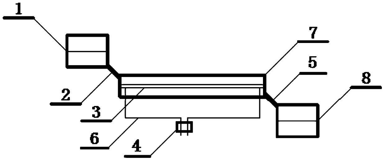
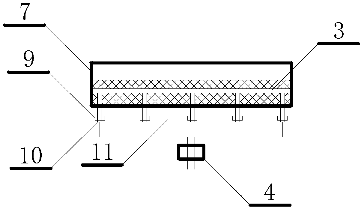
[0035] A slag drainage device for slag wool and a method of use, such as figure 1 , figure 2 As shown, the heater 3 (10mm diameter stainless steel rod) is connected with the power controller 4 through the stainless steel support rod 10 and the heating wire 6, and the insulating gasket 9 can ensure the insulation between the support rod 10 and the support plate 11 to ensure Overall device safety.

[0036] The installed heater 3 has the same length as the slag tapping tank 7. After inspection, there is no leakage between the slag tapping tank 7, the heater 3, and the support plate 11.

[0037] When the slag flows from the slag container 1 through the slag guide groove 2 into the slag groove 7, the temperature is about 1550°C, the slag completely submerges the heater 3, and the height of the center of the heater 3 is 1 / 1 of the height of the slag liquid level. 2. When 220V AC is supplied, the heat emitted by the heater 3 keeps the surrounding slag above 1450°C. The slag has g...

Embodiment 2

[0039] A slag drainage device for slag wool and a method of use, such as figure 1 , figure 2 As shown, the heater 3 (side length is 8mm Q235 square steel) is connected with the power controller 4 through the stainless steel support rod 10 and the heating wire 6, and the insulating gasket 9 can ensure that the support rod 10 and the support plate 11 are kept insulated. Ensure the safety of the overall device.

[0040] The installed heater 3 is slightly shorter than the slag tapping tank 7. After inspection, there is no leakage between the slag tapping tank 7, the heater 3 and the support plate 11.

[0041] When the slag flows from the slag container 1 through the slag guide groove 2 into the slag groove 7, the temperature is about 1530°C, the slag completely submerges the heater 3, and the center height of the heater 3 is 1 / 1 of the height of the slag liquid surface. 3. After the 220V direct current is supplied, the heat emitted by the heater 3 keeps the surrounding slag ab...


PUM

PropertyMeasurementUnit
diameteraaaaaaaaaa

Abstract

The invention relates to a molten slag drainage device for slag wool and a use method thereof. The device comprises a slag discharge container, a slag discharge spout, a slag receiving container; the slag discharge container is connected at an inlet end of the slag discharge spout through a slag discharge guide slot; an outlet end of the slag discharge spout is connected with the slag receiving container through a slag receiving guide slot; the slag discharge spout is internally provided with a heater, and the heater is parallel to the flowing direction of molten slag in the slag discharge spout; the lower ends of supporting rods at both ends of the heater are connected with a power controller by heating wires, and the power controller is connected with a power supply; the molten slag enters the slag discharge container through a blast furnace slagging port, enters the slag discharge spout through the slag discharge guide slot, is heated in the slag discharge spout, keeps good liquidity, and is directly used for slag wool production through the slag receiving guide slot and the slag receiving container. The molten slag can flow in relatively long distance without solidification, long-distance transport of the molten slag is achieved, and the process cost for directly producing products from the molten slag is decreased significantly.

Description

technical field [0001] The invention relates to the technical field of metallurgical slag, in particular to a slag drainage device for slag wool and a method for using the same. Background technique [0002] Molten blast furnace slag is one of the main by-products of blast furnaces and a major component of steel plant waste slag. Usually, each ton of molten blast furnace slag contains (126~188)×10 4 The sensible heat of kJ is equivalent to the energy of 30-40kg heavy oil, and it has a relatively high temperature, about 1450-1600 ℃, which is a high-quality waste heat resource and has a high recycling value. Recovering this part of sensible heat will reduce production costs and create economic benefits for enterprises. [0003] At present, most of the blast furnace slag at home and abroad is water quenched. Although a small amount of heat can be recovered in the form of residual hot water, most of the energy cannot be recovered, resulting in huge energy waste. The direct pr...

Claims


Application Information

Patent Timeline
Patent Type & Authority Patents(China)
IPC IPC(8): C03B37/00
Inventor 王向锋马光宇徐鹏飞刘常鹏李卫东张天赋于淑娟张大奎侯洪宇耿继双钱峰
Owner ANGANG STEEL CO LTD
Why Eureka
Try Eureka