Reservoir area floating garbage collecting device

A technology for garbage collection and reservoir areas, applied in water conservancy projects, cleaning of open water surfaces, construction, etc., can solve problems such as high labor intensity, high labor cost, hidden safety hazards, etc., and achieve the effect of safe and reliable operation and low labor intensity

Active Publication Date: 2017-01-04
MARINE FISHERIES RES INST OF ZHEJIANG
View PDF5 Cites 6 Cited by
  • Summary
  • Abstract
  • Description
  • Claims
  • Application Information

AI Technical Summary

Problems solved by technology

[0004] The purpose of the present invention is to overcome the problem of high labor cost and high labor intensity and certain potential safety hazards in the prior art of cleaning floating garbage in the reservoir area by manual salvage, and to provide an automatic and continuous Clean up the floating garbage accumulated in the reservoir area and other water areas, and the floating garbage collection device in the reservoir area has low labor intensity and safe and reliable operation

Method used


Image

  • Reservoir area floating garbage collecting device
  • Reservoir area floating garbage collecting device
  • Reservoir area floating garbage collecting device

Examples


Embodiment Construction

[0023] Below in conjunction with accompanying drawing and specific embodiment the present invention is described in further detail:

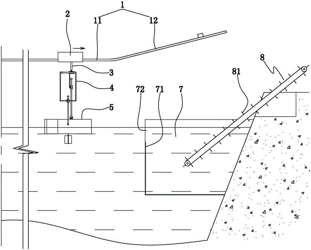
[0024] Such as figure 1 As shown, a floating garbage collection device in the reservoir area includes a driving track 1 located above the water surface, a driving trolley 2 that can walk along the driving track, and a garbage cleaning device. The driving track includes a horizontal track 11 and inclined tracks 12 located at both ends of the horizontal track, and the inclined track extends obliquely upward from the end of the horizontal track. The inclined tracks located at both ends of the horizontal track are arranged symmetrically. The driving track of this embodiment extends along the left-right direction.

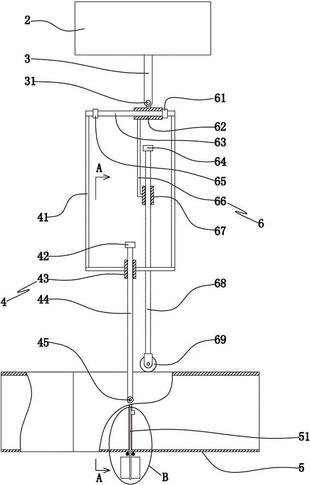
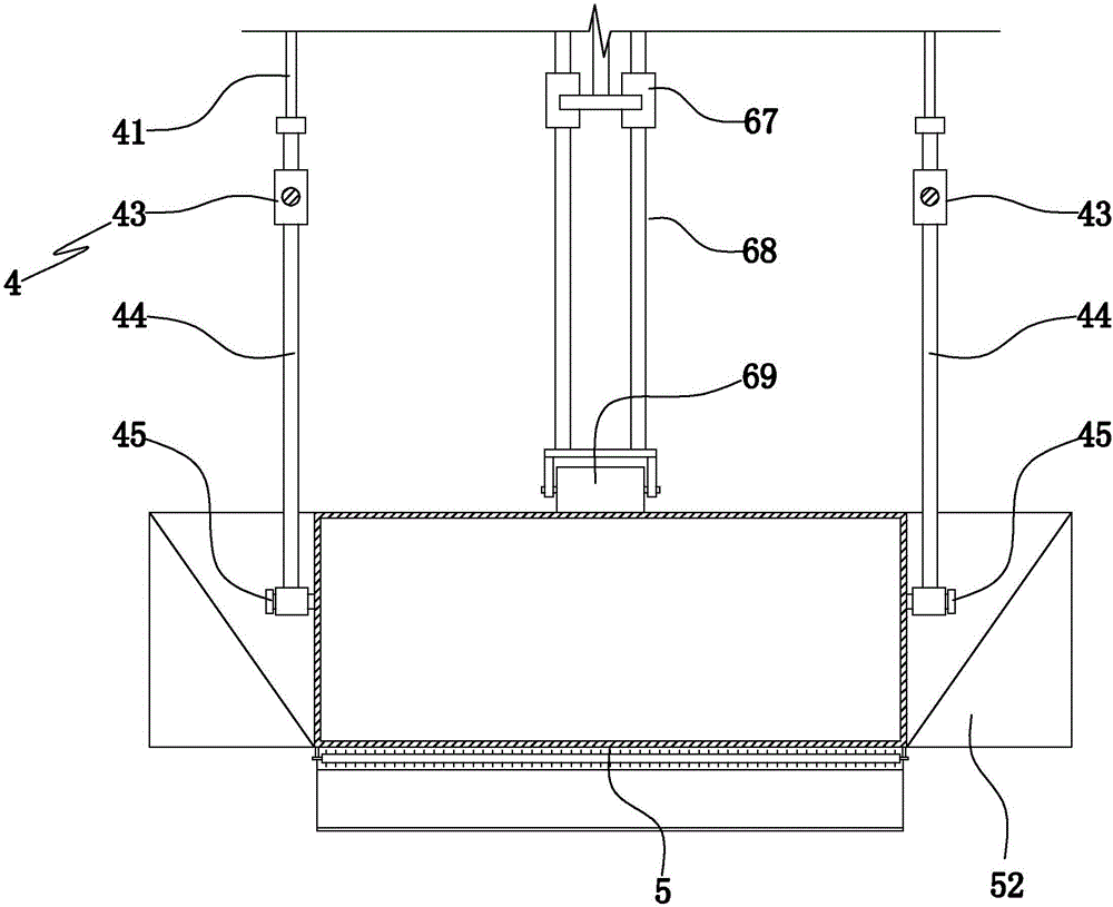
[0025] Such as figure 2 , image 3 As shown, the garbage cleaning device includes a garbage collection casing 5 floating on the water surface and a connection structure connecting the driving trolley and the garbage collection casing...


PUM


Abstract

The invention discloses a reservoir area floating garbage collecting device, and aims at providing a reservoir area floating garbage collecting device which can clear up floating garbage assembling in water areas such as reservoirs automatically and continuously and is low in labor intensity and safe and reliable in operation. The reservoir area floating garbage collecting device comprises a traveling rail located above a water surface, a driving trolley capable of traveling along the traveling rail and a garbage cleaning device, wherein the garbage cleaning device comprises a garbage collecting sleeve body floating on the water surface and a connecting framework for connecting the driving trolley with the garbage collecting sleeve body; openings are formed in the left end and right end of the garbage collecting sleeve body; two guide slots extending upwards and downwards are respectively formed in the middle parts of two opposite side surfaces of the garbage collecting sleeve body; filtering screen plates which can slide upwards and downwards along the guide slots are arranged in the garbage collecting sleeve body; garbage collecting areas formed by enclosure of the screen plates are located in the water areas below the two ends of the travelling rail; and gaps for passing of the garbage collecting sleeve body are formed in the screen plates for forming the garbage collecting areas by enclosure.

Description

technical field [0001] The invention relates to a device for cleaning floating garbage on water, in particular to a device for collecting floating garbage in a reservoir area. Background technique [0002] Due to the lack of people's awareness of environmental protection and the repeated prohibition of illegal dumping of garbage, a large amount of solid floating garbage has been produced in rivers and other waters, causing serious pollution to water quality, which has caused great harm to the water environment and aquaculture. Impact; especially in reservoirs (river-type reservoirs) and other aquaculture areas are often areas where a large amount of floating garbage accumulates, and a large amount of garbage accumulates at the gate of the reservoir area, which will not only cause water pollution, but also affect the flood control of water conservancy projects. [0003] At present, the way to clean up floating garbage in reservoir areas (such as reservoirs) is usually by manu...

Claims


Application Information

Patent Timeline
Patent Type & Authority Applications(China)
IPC IPC(8): E02B15/10
CPCE02B15/10
Inventor 鲍静姣薛彬郭远明李铁军
Owner MARINE FISHERIES RES INST OF ZHEJIANG
Why Eureka
Try Eureka