Engine air inlet assembly, engine system and method for preventing engine air inlet pipe from accumulating large ice blocks

A technology of air intake components and engines, which is applied in the direction of engine components, machines/engines, charging systems, etc., and can solve problems that affect car driving performance and car safety.

Inactive Publication Date: 2017-01-04
QOROS
View PDF8 Cites 2 Cited by
  • Summary
  • Abstract
  • Description
  • Claims
  • Application Information

AI Technical Summary

Problems solved by technology

In addition, these moisture can also enter the air intake system through the main air inlet, which w

Method used


Image

  • Engine air inlet assembly, engine system and method for preventing engine air inlet pipe from accumulating large ice blocks
  • Engine air inlet assembly, engine system and method for preventing engine air inlet pipe from accumulating large ice blocks
  • Engine air inlet assembly, engine system and method for preventing engine air inlet pipe from accumulating large ice blocks

Examples


Embodiment Construction

[0082] The engine air intake assembly, the engine system and the method for preventing the accumulation of large ice cubes in the engine air intake pipe according to the present invention will be further described in detail in conjunction with the accompanying drawings and specific embodiments, but the detailed description does not constitute a definition of the present invention. Technical Program Limitations.

[0083] Figure 5 to Figure 8 The structure and state of the engine intake assembly described in the present invention in one embodiment are respectively shown.

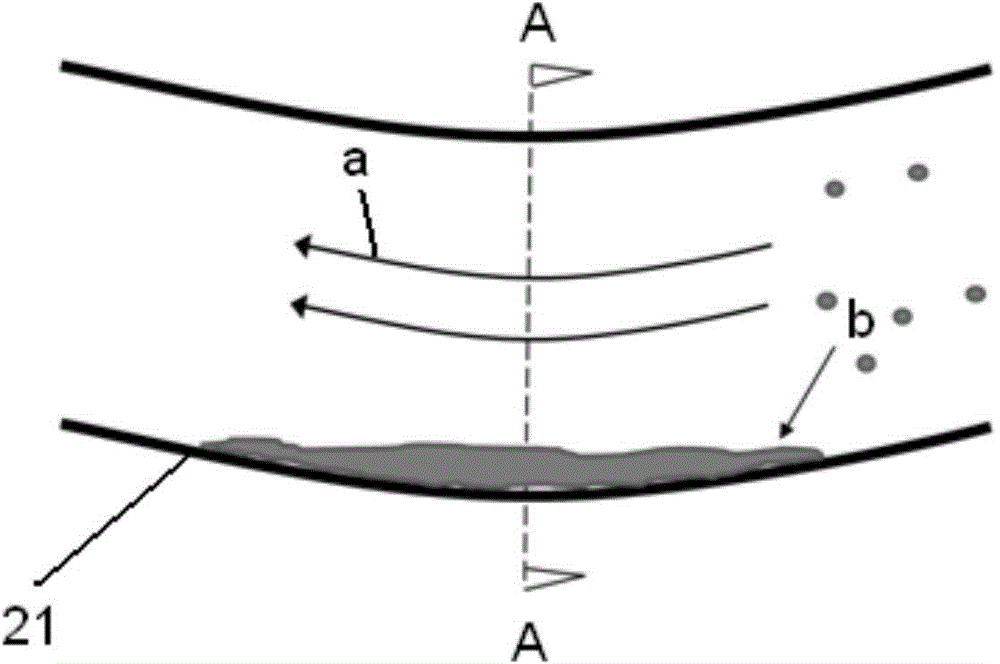
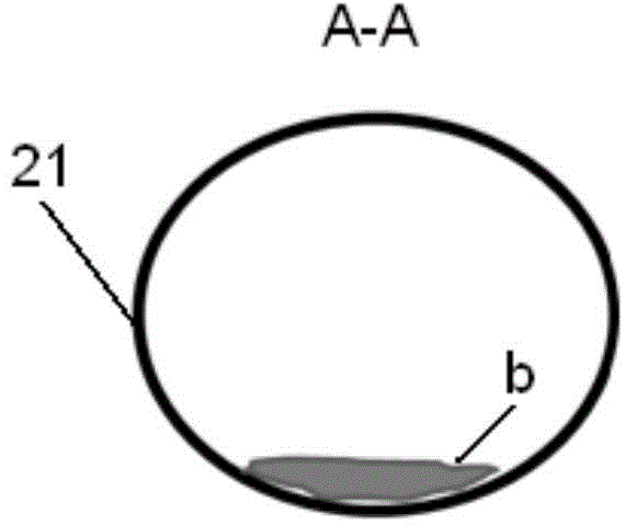
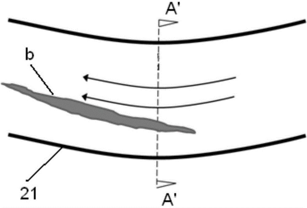
[0084] like Figure 5 to Figure 8 As shown, in the above embodiment, the engine intake assembly includes the engine intake pipe 10 and the heating device 30, wherein, along the gas a flow direction X of the engine intake pipe 10, the engine intake pipe 10 has an intake port 11 and The air outlet port 12 is provided with an ice cube trapping structure 13 at the bottom of the engine intake pipe 10, and the ic...


PUM


Abstract

The invention discloses an engine air inlet assembly. The engine air inlet assembly comprises an engine air inlet pipe, the bottom of the engine air inlet pipe is provided with an ice block gathering structure, and the ice block gathering structure is provided with several ice block gathering grooves. In addition, the engine air inlet assembly also comprises a heating device, and the heating device comprises a first heating element which heats ice blocks gathered in the ice block gathering grooves. The invention also discloses an engine system which comprises any kind of engine air inlet assembly provided by the invention. The invention also discloses a method for preventing an engine air inlet pipe from accumulating large ice blocks. The method comprises that the bottom of the engine air inlet pipe is provided with the ice block gathering structure, the ice block gathering structure is provided with several ice block gathering grooves used for gathering ice blocks, and the heating device is arranged and is controlled to be started under the condition that large ice blocks can be gathered in the engine air inlet pipe in order to thaw large ice blocks which can be gathered. The engine air inlet assembly can thaw gathered ice blocks timely and quickly and then discharge the thawed ice blocks out of the air inlet pipe.

Description

technical field [0001] The invention relates to a gas delivery device, in particular to a gas delivery device for an engine. Background technique [0002] The combustion process of the automotive internal combustion engine will cause some gases (including combustion products and vaporized lubricating oil, collectively referred to as blow-by gas) to enter the crankcase by bypassing the plunger ring. These gases are eventually exhausted from the upper area of ​​the engine into the intake system through the Positive Crankcase Ventilation (PVC) system. This blow-by gas is mixed with the regular air passing through the engine and burned in the subsequent combustion process to ensure that the residual, unburned hydrocarbons in the blow-by gas are fully burned, thereby reducing harmful pollutants of the engine. The blow-by gas includes large amounts of water vapor, which is a major by-product of combustion. [0003] A positive crankcase ventilation system for a turbocharged engin...

Claims


Application Information

Patent Timeline
IPC IPC(8): F02M35/104
Inventor 彦斯·贝肯丁力·罗伯特胡壮丰
Owner QOROS
Why Eureka
Try Eureka