Crankshaft for refrigeration compressor

A technology for refrigeration compressors and crankshafts, applied in the field of crankshafts, can solve problems such as oil film instability, roughening, and oil film damage, and achieve the effects of reducing roughening failures, avoiding roughening, and improving reliability

Active Publication Date: 2017-01-04
JIAXIPERA COMPRESSOR
View PDF7 Cites 1 Cited by
  • Summary
  • Abstract
  • Description
  • Claims
  • Application Information

AI Technical Summary

Problems solved by technology

After analyzing the fault, it is found that the liquid refrigerant in the refrigerator system flows back into the compressor from the suction pipe, which may cause the solubility of the refrigerant in the lubricating oil to be close to saturation, and the lubricating oil and the liquid refriger

Method used


Image

  • Crankshaft for refrigeration compressor
  • Crankshaft for refrigeration compressor
  • Crankshaft for refrigeration compressor

Examples


Embodiment Construction

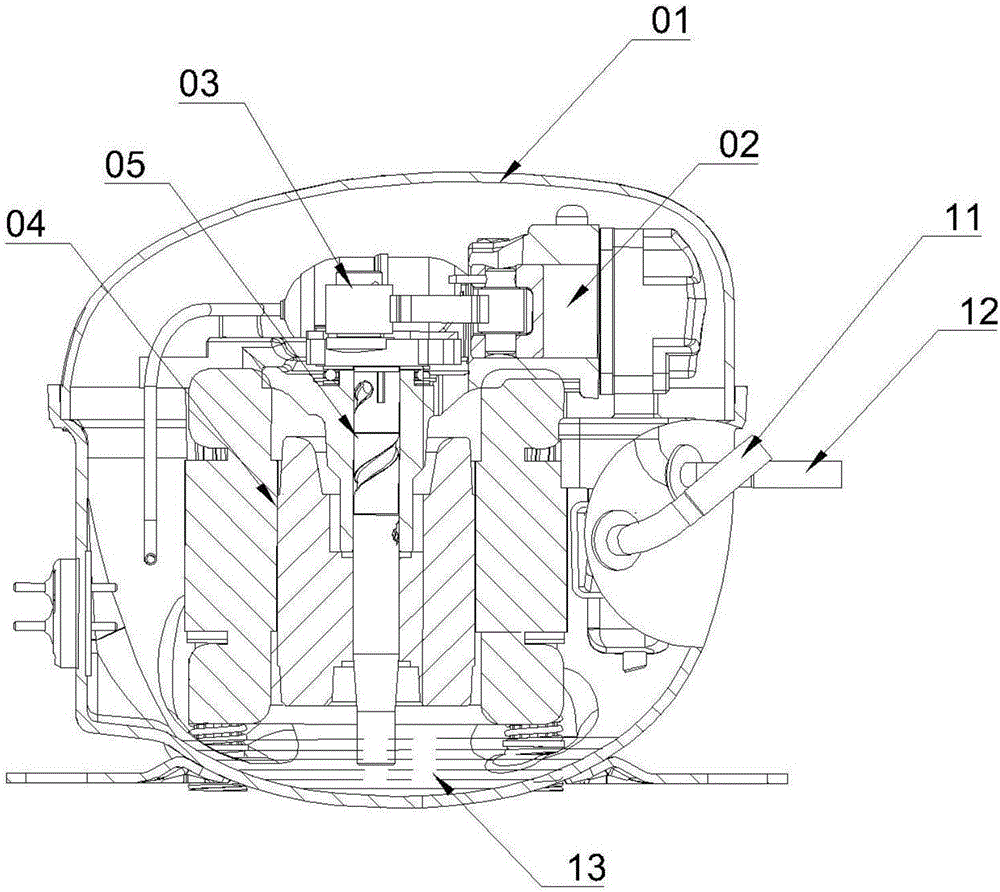
[0014] like figure 1 As shown in , the refrigeration compressor adopting the crankshaft of the present invention includes a closed casing 01, a piston-cylinder unit 02, a crankshaft-connecting rod mechanism 03 and a motor unit 04. The shell 01 is provided with a suction pipe 11 and an exhaust pipe 12. The refrigerant enters the piston-cylinder unit 02 through the suction pipe 11, and the motor unit 04 drives the crankshaft-connecting rod mechanism 03, driving the piston-cylinder unit 02 to reciprocate. The compressed refrigerant is discharged from the compressor shell 01 through the discharge pipe 12 .

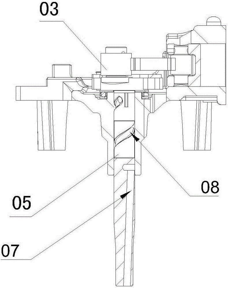
[0015] Please also see figure 2 The crankshaft 05 of the present invention in the crankshaft-connecting rod structure 03 includes a centrifugal pump 07 and a viscous pump 08. The centrifugal pump 07 can be integral or pressed into the oil suction pipe, and the refrigerating oil 13 is transported upwards by centrifugal action.

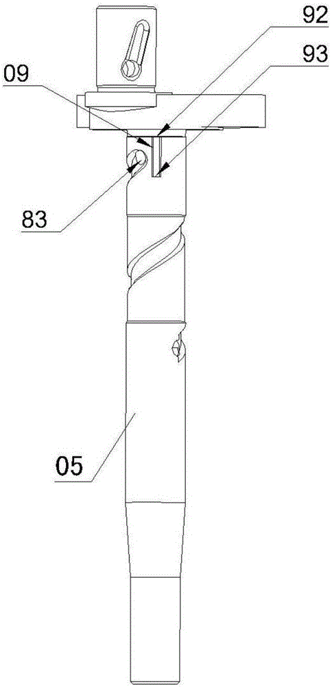
[0016] like image 3 and Figure 4 As shown,...


PUM


Abstract

The invention discloses a crankshaft for a refrigeration compressor, comprising a centrifugal pump and a viscous pump, wherein an oil groove of the viscous pump is formed in the outside surface of the crankshaft, a vent groove is formed in the friction surface of a long shaft of the viscous pump, the opening of the vent groove is formed in a tool withdrawal groove area at the top of the long shaft of the crankshaft, and the vent groove extends downwards along the machining area of the crankshaft. Air-fuel mixed gas of the crankshaft area easy to wear can be quickly separated at high temperature when the crankshaft works, the separated gas can be discharged out of a friction area through the vent groove, so that a large number of release of refrigerant at a position where fault easily occurs can be carried out, and galling caused by breakdown of an oil film can be avoided. Meanwhile, the vent groove also can serve as an oil storage tank, the lubrication between kinematic pairs can be guaranteed, the fault of the galling near an oil hole in the crankshaft is further reduced, and the reliability of the compressor is improved.

Description

technical field [0001] The invention relates to the technical field of refrigeration compressors, in particular to a crankshaft used in refrigerator refrigeration compressors. Background technique [0002] The refrigeration compressor is usually arranged at the bottom of the rear side of the refrigerator, and its function is to compress and transport the circulating refrigerant in the refrigerator system, thereby transferring heat from the interior of the refrigerator to the surrounding environment. The refrigerator compressor drives the crankshaft-connecting rod movement mechanism through the motor, and then drives the piston-cylinder unit to compress the refrigerant. The crankshaft of the compressor has the function of pumping oil. On the one hand, it can lubricate the crankshaft-connecting rod-piston movement mechanism to prevent the movement mechanism from being stuck; on the other hand, it can cool the piston-cylinder unit. The bottom of the compressor shell is provide...

Claims


Application Information

Patent Timeline
IPC IPC(8): F04B39/00F04B39/02
CPCF04B39/0094F04B39/02
Inventor 张勤建张韦林苗锋徐飞宋国华
Owner JIAXIPERA COMPRESSOR
Why Eureka
Try Eureka