
Reducer gear box for angle rotation limit

A technology of rotation limit and tooth box, which is applied in the direction of transmission, transmission parts, gear transmission, etc., can solve the problem of limit reliability, control accuracy and service life reduction, hinder the technical progress of the reduction tooth box, and affect the speed reduction tooth Box limit function and other issues, to achieve the effect of easy promotion and application, easy implementation, and simple structure

Active Publication Date: 2018-08-24
RESTAR GRP
View PDF5 Cites 0 Cited by
  • Summary
  • Abstract
  • Description
  • Claims
  • Application Information

AI Technical Summary

Problems solved by technology

[0004] The traditional way of limiting the rotation angle of the reduction tooth box generally uses a travel switch to control the output rotation angle and realize the limit. The basic principle is that the controller controls the motor and finally controls the rotation angle of the output gear according to the travel switch signal. Its structure It is cumbersome, the production and assembly are more complicated, and the limit function of the entire reduction gearbox will be affected by the quality and operational reliability of the limit switch, resulting in a reduction in the limit reliability, control accuracy and service life, which hinders the application of the reduction gearbox technological advances in the field

Method used


Image

  • Reducer gear box for angle rotation limit
  • Reducer gear box for angle rotation limit
  • Reducer gear box for angle rotation limit

Examples


Embodiment Construction

[0024] The present invention will be further explained below in conjunction with the drawings:

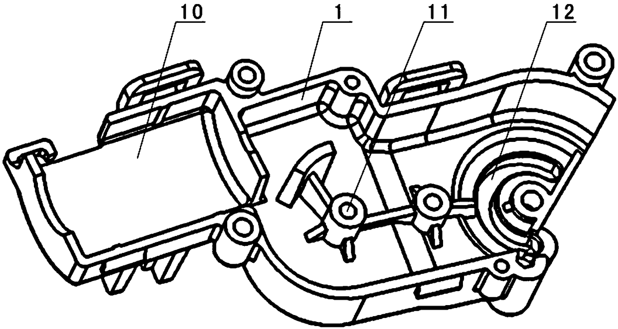
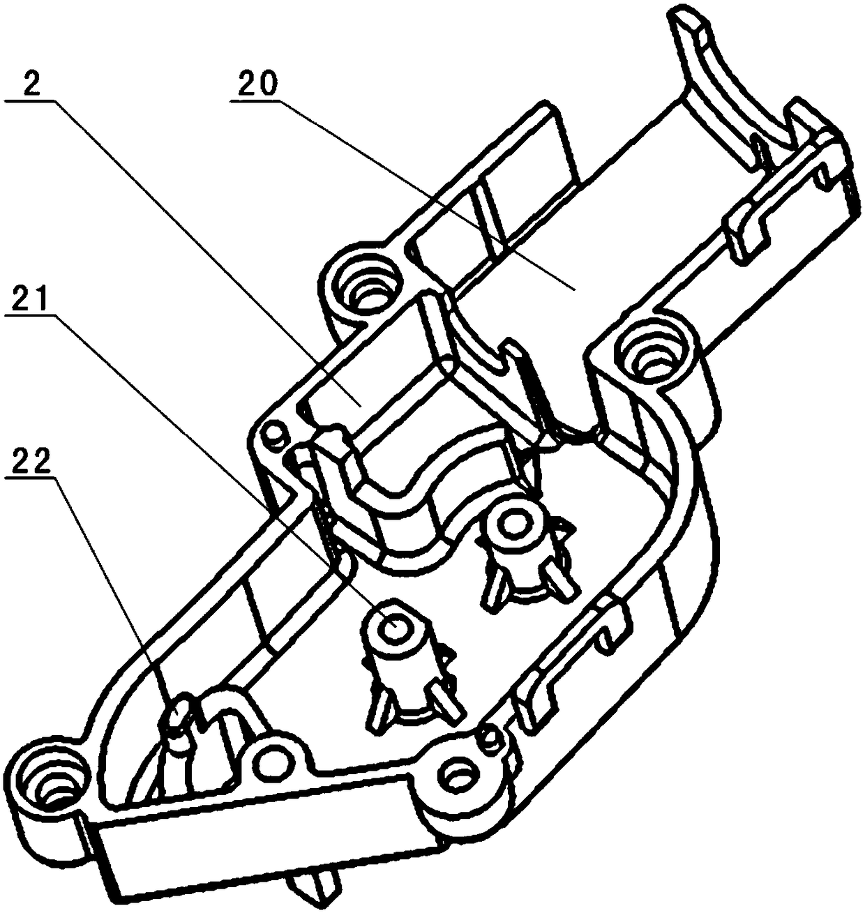
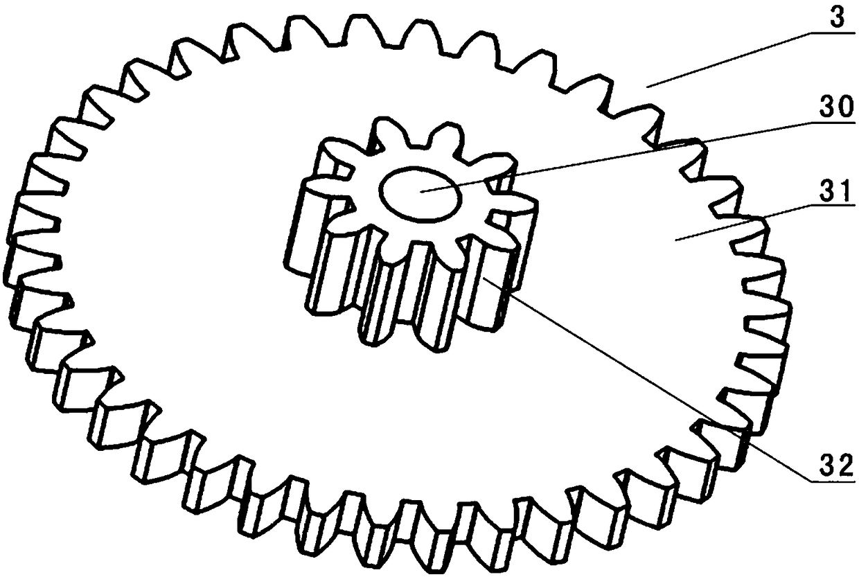
[0025] Such as Figure 1-Figure 9 As shown, the deceleration tooth box for facilitating angular rotation limit of the present invention includes a first tooth box cover 1 and a second tooth box cover 2 which are connected to each other, and are placed on the first tooth box cover 1 and the second tooth box cover The transmission gear between the cover 2 and the motor 6. The transmission gear includes a worm gear 7, a transition gear 3, a clutch gear 4 and an output gear 5. The worm gear 7 is sleeved on the shaft of the motor 6 through its own central through hole. The gear 3 includes a large-diameter transition gear 31 and a small-diameter transition gear 32 that are coaxial and connected to each other. The circumferential outer teeth of the large-diameter transition gear 31 are meshed with the circumferential outer teeth of the worm gear 7, and the third central shaft 81 passes throu...


PUM


Abstract

The invention discloses a novel speed-reducing gear box facilitating angle rotation limiting. The novel speed-reducing gear box comprises a first gear box cover, a second gear box cover and a drive gear, wherein the first gear box cover and the second gear box cover are connected mutually, the drive gear comprises a clutch gear and an output gear, the clutch gear comprises a large-diameter clutch gear and a small-diameter clutch gear, circumferential outer teeth of the large-diameter clutch gear are driven by a motor, the output gear comprises a large-diameter output gear and a small-diameter output gear which are coaxial and are mutually and fixedly connected through the inner end faces, the large-diameter output gear is in meshed connection with the small-diameter clutch gear, the circumferential outer teeth of the small-diameter output gear are rotary power output teeth of the speed-reducing gear box, and a forward rotary limiting device and a reverse rotation limiting device respectively matched with the first gear box cover and the second gear box cover are arranged on the output gear. The novel speed-reducing gear box is provided with the clutch gear and the output gear which are mutually matched, utilizes the output gear to achieve accurate rotation angle limiting and has the advantages of being high in limiting reliability, high in control accuracy and long in service life.

Description

Technical field [0001] The invention relates to a reduction gear box, in particular to a reduction gear box which is convenient for angular rotation limit. Background technique [0002] The tooth box is a gearbox, which is a device that increases or reduces the rotation by meshing gears of different sizes. It includes at least a tooth box shell and a plurality of transmission gears placed in the tooth box shell. The tooth box shell generally includes interconnected Under the first tooth box cover and the second tooth box; the motor for generating rotation power can be placed in the tooth box shell or outside the tooth box shell. [0003] The gearbox is a gearbox that achieves the purpose of reducing the speed through multiple transmissions. It is widely used in industries and life where the speed needs to be reduced. For example, some more realistic toy cars, especially deformed toy cars, need to be opened and closed. Driven by a motor, there is a gear box between the motor and th...

Claims


Application Information

Patent Timeline
Patent Type & Authority Patents(China)
IPC IPC(8): F16H3/087F16H57/023
CPCF16H3/087F16H57/023
Inventor 陈雁升
Owner RESTAR GRP
Learn More