Four-in-one speed reducer

A technology of reducer and clutch, applied in the direction of toothed element, belt/chain/gear, mechanical equipment, etc., can solve the problem of inconvenient movement, and achieve the effect of low manufacturing cost, saving installation space and simple structure

Pending Publication Date: 2017-01-04
湖北咸宁三合机电股份有限公司
View PDF0 Cites 0 Cited by
  • Summary
  • Abstract
  • Description
  • Claims
  • Application Information

AI Technical Summary

Problems solved by technology

[0002] The existing reducers include three-in-one reducer, planetary reducer, connecting rod reducer, three-ring reducer, etc. These reducers are generally equipped with motors and brakes and used at the same time. At present, these reducers can transmit torque and play a role in deceleration. , but when the machine is stopped, it is inconvenient to use manpower to move the working mechanism after the output shaft of the reducer

Method used


Image

  • Four-in-one speed reducer
  • Four-in-one speed reducer

Examples


Embodiment Construction

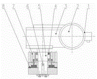
[0013] Instructions attached figure 1 As shown in the figure: the driving end of the normally open electromagnetic clutch 8 is fixed on the outer end of the output shaft 5 of the reducer, and is connected to the output shaft 5 of the reducer through a flat key 6; the output gear 7 is connected to the output shaft 5 through a rolling bearing 4, and the output gear 7 is fixedly connected with the driven end of the normally open electromagnetic clutch 8, and can rotate around the output shaft 5 of the reducer when the output shaft 5 of the reducer is not rotating; the output shaft 5 of the reducer is the Output shaft;

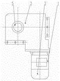
[0014] Instructions attached figure 2 Shown in: the brake 2 and the motor 1 are made into one.

[0015] The working process of the four-in-one reducer: when the power source is input from the motor 1, the brake 2 releases the brake, the normally open electromagnetic clutch 8 is energized and combined, and the output shaft 5 of the reducer transmits the torque t...


PUM


Abstract

The invention relates to a four-in-one speed reducer. The four-in-one speed reducer comprises a motor, a brake, a speed reducer body, a rolling bearing, a speed reducer output shaft, a flat key, an output gear and a normally-open electromagnetic clutch. The four-in-one speed reducer is characterized in that the motor and the brake are arranged in the power input end of the speed reducer body, and the normally-open electromagnetic clutch is arranged on the speed reducer output shaft of the speed reducer body; and the normally-open electromagnetic clutch can transmit the torque when powered on, the normally-open electromagnetic clutch is separated when powered off and cannot transmit the torque, however, the output gear can be rotated manually to make the subsequent mechanism move, and thus using requirements are met. The four-in-one speed reducer is reasonable in design, compact in structure and can be widely applied to transmission of various machines.

Description

technical field [0001] The invention relates to a four-in-one reducer. Background technique [0002] The existing reducers include three-in-one reducer, planetary reducer, connecting rod reducer, three-ring reducer, etc. These reducers are generally equipped with motors and brakes and used at the same time. At present, these reducers can transmit torque and play a role in deceleration. , but when the machine is stopped, it is inconvenient to use manpower to make the working mechanism after the output shaft of the reducer move. Contents of the invention [0003] The purpose of the present invention is to design and manufacture a working mechanism behind the output shaft of the reducer when the reducer is shut down, which can still be operated by manual external force, so as to make up for the shortcomings of the existing reducer. [0004] The technical solution adopted by the present invention to solve its technical problems is: [0005] An electric motor and a brake are ...

Claims


Application Information

Patent Timeline
IPC IPC(8): F16H61/32
CPCF16H61/32
Inventor 万名炎余海明
Owner 湖北咸宁三合机电股份有限公司
Why Eureka
Try Eureka