Multifunctional automobile chassis component test bench

A technology of automobile chassis and components, applied in the field of test benches, can solve the problems of inconvenient up and down adjustment and inability to adjust accurately, and achieve the effects of convenient adjustment, improved precision, and improved work efficiency

Inactive Publication Date: 2017-01-04
ZHEJIANG GEELY HLDG GRP CO LTD +1
View PDF9 Cites 6 Cited by
  • Summary
  • Abstract
  • Description
  • Claims
  • Application Information

AI Technical Summary

Problems solved by technology

[0003] In the existing automobile chassis structural parts test bench, the equipment actuator is installed at the long waist hole of the foundation fixing bracket, and the actuator can only be fixed at the rear end. When adjusting the position of the actuator, it can only be lifted up and down by hand. Adjustment, with the disadvantage of inconvenient up and down adjustment and impossibility of precise adjustment

Method used


Image

  • Multifunctional automobile chassis component test bench
  • Multifunctional automobile chassis component test bench
  • Multifunctional automobile chassis component test bench

Examples


Embodiment 1

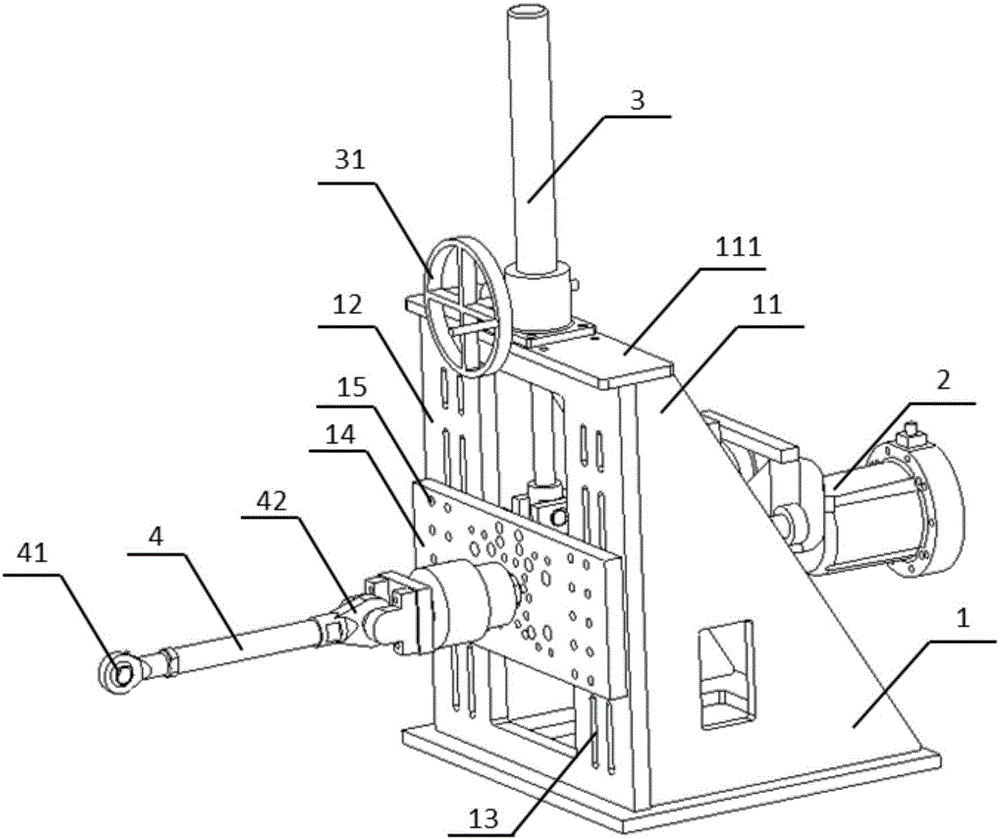
[0050] figure 1 It is a structural schematic diagram of a multifunctional automobile chassis parts test bench according to an embodiment of the present invention.

[0051] In this embodiment, the test bench for multifunctional automobile chassis components may include: a basic fixing bracket 1 , an actuator 2 , a lifting mechanism 3 and a connecting rod 4 .

[0052]The basic fixed support 1 is used to support the whole actuator 2, and it has a door frame type support 11, and one end surface of the door frame type support 11 is provided with a fixed plate 12 along its longitudinal direction, and the fixed plate 12 is arranged along its The waist hole 13 that length direction is provided with. The actuator 2 is installed at the base fixing bracket 1 for providing driving force to the test bench. The lifting mechanism 3 is detachably installed on the top 111 of the door frame-shaped support 11 and passes through the top 111 and is connected with the actuator 2 for driving the a...

Embodiment 2

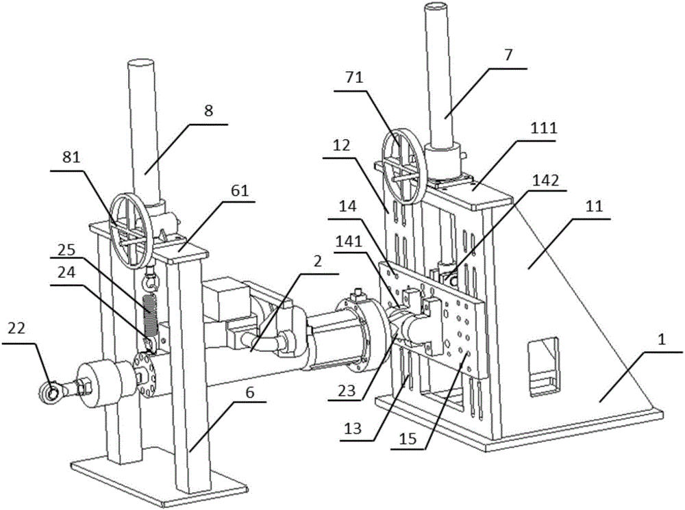
[0066] figure 2 It is a structural schematic diagram of a multifunctional automobile chassis parts test bench according to another embodiment of the present invention. In this embodiment, the multifunctional automobile chassis parts test bench may include: a basic fixed support 1 , a fixed support 6 , an actuator 2 , a first lifting mechanism 7 and a second lifting mechanism 8 .

[0067] The basic fixed support 1 is used to support the whole actuator 2, and it has a door frame type support 11, and one end surface of the door frame type support 11 is provided with a fixed plate 12 along its longitudinal direction, and the fixed plate 12 is arranged along its The waist hole 13 that length direction is provided with. The fixed bracket 6 is arranged in front of the basic fixed bracket 1 along the transverse axis thereof, and is used to support the entire actuator 2 together with the basic fixed bracket 1 . The actuator 2 is installed between the base fixing bracket 1 and the fi...


PUM


Abstract

The invention discloses a multifunctional automobile chassis component test bench, relates to a test bench. The test bench comprises a basic fixed bracket for supporting a whole actuator, the actuator for providing driving force to the test bench frame, a lifting mechanism which is removably arranged on the basic fixed bracket and is used for driving the actuator to actuator to carry out up and down precise adjustment, a connection rod which is connected to the actuator, and a control system which is electrically connected to the actuator and is used for precisely controlling the driving power needed by a test. According to the multifunctional automobile chassis component test bench, through the control system and the lifting mechanism, the driving of the whole actuator is precisely controlled, thus the whole test bench is more intelligent and accurate, the precise adjustment of the actuator is realized, and the test precision and working efficiency are improved. By using different modes, the actuator is fixedly connected, the test bench can test the stiffness, strength and durability of different automobile chassis components, the use of the multifunctional automobile chassis component test bench is flexible, and the application range of the test bench is increased.

Description

technical field [0001] The invention relates to a test stand, in particular to a test stand for multifunctional automobile chassis components. Background technique [0002] With the development of science and technology and the progress of the economy, the demand for automobiles is increasing, and the requirements for the safety performance of automobiles are also getting higher and higher. The performance of automobile chassis parts plays a very important role in the overall safety performance of the car. Therefore, after production, automobile chassis parts will undergo a series of tests to meet safety standards. [0003] In the existing automobile chassis structural parts test bench, the equipment actuator is installed at the long waist hole of the foundation fixing bracket, and the actuator can only be fixed at the rear end. When adjusting the position of the actuator, it can only be lifted up and down by hand. Adjustment has the disadvantages that it is inconvenient to...

Claims


Application Information

Patent Timeline
Patent Type & Authority Applications(China)
IPC IPC(8): G01M17/007
CPCG01M17/007
Inventor 董远明杨国斌赵子顺张晓东
Owner ZHEJIANG GEELY HLDG GRP CO LTD
Why Eureka
Try Eureka