Equipment for quantum dot test paper quality inspection and use method of equipment

A technology of test strips and quantum dots, which is applied in the field of quality inspection equipment for quantum dot test strips, can solve problems such as inability to guarantee product consistency and product quality stability, and achieve accurate and reliable test results, consistency and quality assurance Stability and the effect of improving production efficiency

Active Publication Date: 2017-01-04
JIANGSU LIANGDIAN TECH CO LTD
9 Cites 1 Cited by

AI-Extracted Technical Summary

Problems solved by technology

However, the current quality inspection of quantum dot test strips mainly relies on manual quality inspection, which cannot guarantee product consis...

Abstract

The invention provides equipment for quantum dot test paper quality inspection. The equipment comprises a camera obscura, a bearing device, a light source device and a signal acquisition device, wherein the bearing device is arranged inside the camera obscura and is used for holding a piece of quantum dot test paper; at least one positioning reference is arranged on the bearing device; the light source device is arranged inside the camera obscura and is used for radiating and exciting the quantum dot test paper and the positioning reference to emit fluorescent light; the signal acquisition device is arranged inside the camera obscura and is used for collecting the fluorescent light for performing quality inspection on the quantum dot test paper according to the fluorescent light. The invention further provides a method using the equipment for quantum dot test paper quality inspection. The equipment for quantum dot test paper quality inspection, which is provided by the invention, can be applied to automatic in-batch quality inspection on the quantum dot test paper, and by adopting the equipment, the inspection result can be precise and reliable, characteristic consistency and quality stability of a product can be ensured, the production efficiency can be improved, and the production cost can be lowered.

Application Domain

Technology Topic

PhysicsCamera obscura +5

Image

  • Equipment for quantum dot test paper quality inspection and use method of equipment
  • Equipment for quantum dot test paper quality inspection and use method of equipment
  • Equipment for quantum dot test paper quality inspection and use method of equipment

Examples

  • Experimental program(1)

Example Embodiment

[0058] DETAILED DESCRIPTION OF THE PREFERRED EMBODIMENTS The present invention will be further explained in conjunction with the above drawings.
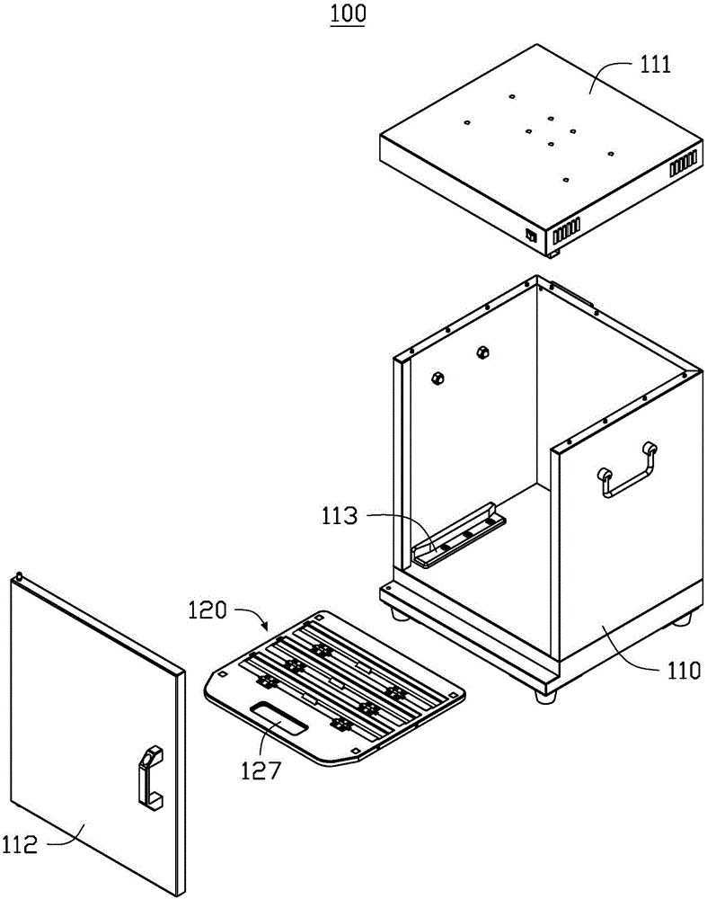
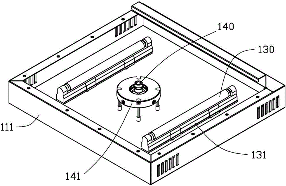
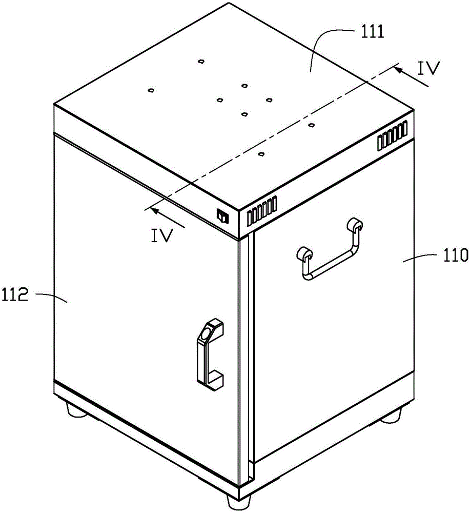
[0059] Such as Figure 1-5 As shown, the apparatus 100 for quality inspection of quantum dot test strips according to the first preferred embodiment of the present invention includes: a dark box 110, a supporting device 120, a light source device 130, and a signal collection device 140.
[0060] The dark box 110 includes a detachable top plate 111 and a door 112 that can be opened and closed. The bottom of the dark box 1 is also provided with a chute 113.
[0061] The supporting device 120 is clamped to the bottom of the dark box 112 through the sliding groove 113, and includes a strip groove 121, a scale area 122 and a reference area 123. In this embodiment, the supporting device 120 is a tray.
[0062] The strip groove 121 is used to place the quantum dot test strip 124. In this embodiment, the number of strip grooves 121 is three.
[0063] The scale area 122 is adjacent to and arranged in parallel with the strip groove 121, and the scale area 122 is used for attaching the scale 125 so as to identify the position of the quantum dot test strip 124 with the quality inspection problem according to the quality inspection result.
[0064] The reference area 123 is located at the edge of the supporting device 120 and is used for placing a positioning reference object 126. In this embodiment, the reference area 123 is located at the four corners of the supporting device 120. The positioning reference 126 is fluorescent paper.
[0065] In this embodiment, the supporting device 120 further includes a handle 127. In this embodiment, the handle 127 is a through hole.
[0066] The light source device 130 is held on the top plate 111 of the dark box 110 by the base 131. The light source device 130 emits light in a wavelength range of 360-450 nm. In this embodiment, the light source device 130 is an ultraviolet lamp.
[0067] The signal collection device 140 is arranged in parallel with the light source device 130, is held on the top plate 111 of the dark box 110 by the base 141 and faces the supporting device 120. In this embodiment, the signal acquisition device 140 is a camera.
[0068] Reference Image 6 The use of the device 100 for quality inspection of quantum dot test strips will be described as follows.
[0069] Such as Image 6 As shown, including the following steps:
[0070] S10. Place the quantum dot test strip 124 and the positioning reference object 126 in the strip groove 113 and the reference area 123 in the supporting device 120, respectively. In this embodiment, the number of quantum dot test strips 124 placed is three.
[0071] S20. Open the box door 112, hold the handle 127 to clamp the supporting device 120 with the quantum dot test strip 124 and the positioning reference object 126 into the bottom of the dark box 110 through the chute 113, fix it, and close the box door 112.
[0072] S30. The light source device 130 emits light waves with a wavelength range of 360-450 nm, illuminates the entire quantum dot test strip 124 and the positioning reference object 126, and excites fluorescence.
[0073] In this embodiment, the light source device 130 irradiates the quantum dot test strip 124 and/or the positioning reference object 126 as an irradiation mode, that is, irradiates the entire supporting device, and the irradiation time is 10 seconds.
[0074] S40. The signal collection device 140 collects the fluorescence excited by the entire quantum dot test strip 124 and the positioning reference object 126 to perform quality inspection on the quantum dot test strip according to the fluorescence.
[0075] In this embodiment, the signal collection device 140 collects fluorescence in a manner that collects fluorescence excited by the quantum dot test strip 124 and the positioning reference 126 as a whole. And the collection time is 10s. Specifically, the signal acquisition device and the light source device are started at the same time, or the signal acquisition device is started 1-2 seconds later than the light source device.
[0076] Figure 7 It shows the second preferred embodiment of the supporting device 150 in the device for quality inspection of quantum dot test strips of the present invention.
[0077] Such as Figure 7 As shown, the supporting device 150 is a tray. The supporting device 150 includes a strip groove 151, a scale area 152, and a reference area 153. The strip groove 151 is used to place the quantum dot test strip 154. In this embodiment, the number of strip grooves 151 is four. The scale area 152 is adjacent to the strip groove 151 and is arranged in parallel, and the scale area 152 is used for attaching the scale 155 so as to identify the position of the quantum dot test strip 154 ​​with the quality inspection problem according to the quality inspection result. The reference area 153 is located at the edge of the supporting device 150 and is used for placing a positioning reference object 156. The reference area 153 surrounds the strip groove 151 and the scale area 152 into a triangle. The supporting device 150 also includes a handheld portion 157. Specifically, the hand-held part is a handle.
[0078] The above-mentioned embodiments are preferred embodiments of the present invention, but the embodiments of the present invention are not limited by the above-mentioned embodiments, and the above-mentioned embodiments are only used to interpret the claims. However, the protection scope of the present invention is not limited to the specification. Any changes or substitutions that can be easily conceived by those skilled in the art within the technical scope disclosed by the present invention are all included in the protection scope of the present invention.

PUM

PropertyMeasurementUnit
Wavelength360.0 ~ 450.0nm
tensileMPa
Particle sizePa
strength10

Description & Claims & Application Information

We can also present the details of the Description, Claims and Application information to help users get a comprehensive understanding of the technical details of the patent, such as background art, summary of invention, brief description of drawings, description of embodiments, and other original content. On the other hand, users can also determine the specific scope of protection of the technology through the list of claims; as well as understand the changes in the life cycle of the technology with the presentation of the patent timeline. Login to view more.

Similar technology patents

Method, device and system for carrying out function detection on hardware-in-loop device

InactiveCN109975032AThe test results are accurate and reliableEasy to findVehicle testingLoop deviceHardware-in-the-loop simulation
Owner:GUANGZHOU XIAOPENG MOTORS TECH CO LTD

Classification and recommendation of technical efficacy words

  • The test results are accurate and reliable
  • Ensure quality stability and consistency

Novel proton exchange reaction furnace and usage

InactiveCN107670619AEnsure quality stability and consistencyGaseous chemical processesChemical/physical/physico-chemical stationary reactorsGlass containerEngineering
Owner:CHONGQING EAGLE VALLEY OPTOELECTRONICS
Why Eureka
Try Eureka