
Back electromotive force measurement device and method of motor

A technology of back electromotive force and measuring device, which is applied in the field of electric motors, can solve problems affecting the accuracy of back electromotive force measurement, increase the complexity of back electromotive force, fast decay of back electromotive force waveform, etc., and achieve reduced measurement cost, high-speed measurement, and simplified measurement methods Effect

Pending Publication Date: 2017-01-04
ZHUHAI LANDA COMPRESSOR +1
View PDF9 Cites 16 Cited by
  • Summary
  • Abstract
  • Description
  • Claims
  • Application Information

AI Technical Summary

Problems solved by technology

Due to the limitation of the input voltage of the oscilloscope, the rated speed of the rotor is required to be low, and because of the damping, the attenuation of the back EMF waveform is faster, which affects the accuracy of the back EMF measurement
At the same time, when the prime mover and the motor are installed, special testing equipment is required to ensure accurate coaxiality and sufficiently small damping between the stator and rotor, and the connection process is cumbersome.
In addition, when measuring the motor back electromotive force of an outsourced product (such as a compressor), the motor needs to be disassembled from the product before the measurement can be performed, which increases the complexity of the back electromotive force measurement

Method used


Image

  • Back electromotive force measurement device and method of motor
  • Back electromotive force measurement device and method of motor
  • Back electromotive force measurement device and method of motor

Examples


Embodiment 1

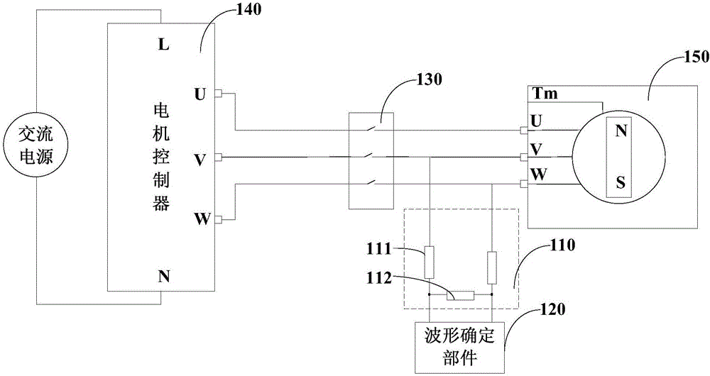
[0029] figure 1 It is a schematic structural diagram of a motor back EMF measurement device provided by Embodiment 1 of the present invention. This embodiment can be applied to the situation where the back EMF value is determined by analyzing the back EMF waveform by providing drive with the help of a controller supporting the motor. Such as figure 1 As shown, the counter electromotive force measuring device specifically includes: a sampling component 110 and a waveform determining component 120 .

[0030] Wherein, the sampling component 110 is connected with the motor stator, and is used to collect the voltage signal between any two phases of the motor stator, wherein, when the rotor speed of the motor 150 reaches a set speed threshold, the motor controller 140 stops Output drive pulse signal. The motor controller 140 is a supporting control device for the motor 150 , for example, it may be a controller such as a frequency converter or a square wave controller. Such as fi...

Embodiment 2

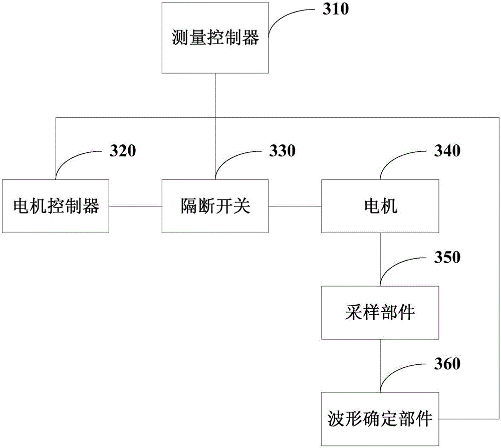
[0049] image 3 It is a structural schematic diagram of the back electromotive force measuring device of the motor in the second embodiment of the present invention. This embodiment is applicable to the situation where the motor controller is automatically controlled to drive the motor, and the waveform of the back electromotive force is collected and analyzed to determine the value of the back electromotive force. Such as figure 1 As shown, the counter electromotive force measurement device specifically includes: a measurement controller 310 , a sampling component 350 , an isolation switch 330 and a waveform determination component 360 .

[0050] The sampling part 350 is connected with the motor stator, and is used to collect the voltage signal between any two phases of the motor stator, wherein the motor 340 operates under the control of the drive pulse signal output by the motor controller 320, so that the motor 340 A stable set speed threshold (which may be rated speed) ...


PUM


Abstract

The invention discloses a back electromotive force measurement device and a method of a motor and relates to the field of motors. The device comprises a sampling part and a waveform determination part. The sampling part is connected with a motor stator and is used for sampling voltage signals between any two phases of the motor stator. When the rotation speed of a rotor of the motor reaches a set speed threshold value, a motor controller stops outputting driving pulse signals. The waveform determination part is electrically connected with the sampling part and is used for acquiring the voltage signals acquired by the sampling part so as to determine waveforms of the voltage signals corresponding to the motor stator after the motor controller stops outputting the driving pulse signals to determine a value of back electromotive force according to the waveforms corresponding to the back electromotive force of the motor. According to the technical scheme provided by the invention, current measurement modes are simplified and an effect of improving measurement precision is achieved.

Description

technical field [0001] Embodiments of the present invention relate to motor technology, and in particular to a device and method for measuring back electromotive force of a motor. Background technique [0002] Permanent magnet synchronous motors are widely used in industry, transportation and household appliances because of their advantages such as high efficiency, high torque, high power density and good speed regulation performance. [0003] Back EMF is an important parameter for the control of permanent magnet synchronous motor. At this stage, the no-load back electromotive force of the permanent magnet synchronous motor is generally measured by adding an external prime mover or manually accelerating the rotor. For example, the prime mover is used to drive the permanent magnet synchronous motor to make the rotor reach the rated speed, the permanent magnet synchronous motor stator is open, and the stator voltage is measured by an oscilloscope to measure the no-load back e...

Claims


Application Information

Patent Timeline
Patent Type & Authority Applications(China)
IPC IPC(8): G01R19/00G01R31/34
CPCG01R19/0084G01R31/34
Inventor 汪田华范少稳尹伟锋
Owner ZHUHAI LANDA COMPRESSOR
Features
  • Generate Ideas
  • Intellectual Property
  • Life Sciences
  • Materials
  • Tech Scout
  • Unparalleled Data Quality
  • Higher Quality Content
  • 60% Fewer Hallucinations
Learn More