Bracket, backlight module and liquid crystal display device

A backlight module and bracket fixing technology, applied in optics, nonlinear optics, instruments, etc., can solve the problems of difficult disassembly, long time consumption, etc., and achieve the effect of simple operation, short time consumption, fast installation and disassembly

Active Publication Date: 2017-01-04
HISENSE VISUAL TECH CO LTD
View PDF5 Cites 1 Cited by
  • Summary
  • Abstract
  • Description
  • Claims
  • Application Information

AI Technical Summary

Problems solved by technology

[0005] Based on the deficiencies of the prior art, the object of the present invention is to provide a bracket, a backlight module and a liquid crystal display device, thereby solving the problems of difficult

Method used


Image

  • Bracket, backlight module and liquid crystal display device
  • Bracket, backlight module and liquid crystal display device
  • Bracket, backlight module and liquid crystal display device

Examples


Embodiment 1

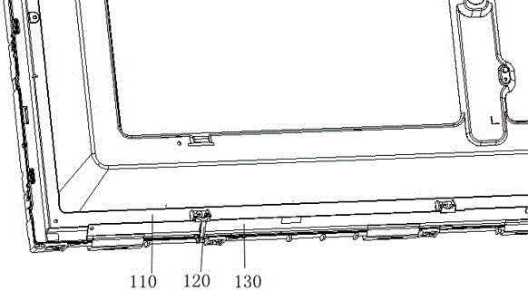
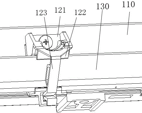
[0039] Embodiment 1 of the present invention provides a bracket fixing member and a backlight module. The backlight module can be applied to the fixing of functional brackets in any liquid crystal display device. For the convenience of description, the embodiment 1 of the present invention selects the fixing scheme of the Source board for illustration. Figure 5 It is a structural schematic diagram of the backlight module in Embodiment 1 of the present invention.

[0040] It should be noted that, in addition to the backlight module provided in Embodiment 1 of the present invention Figure 5~Figure 14 In addition to the structure shown, it also includes at least a light source, a plastic frame, a light guide plate, and other optical films. Regarding other components of the backlight module in this embodiment 1, the present invention does not specifically limit it. Those skilled in the art can refer to existing There is a specific structure of the backlight module in the art. ...

Embodiment 2

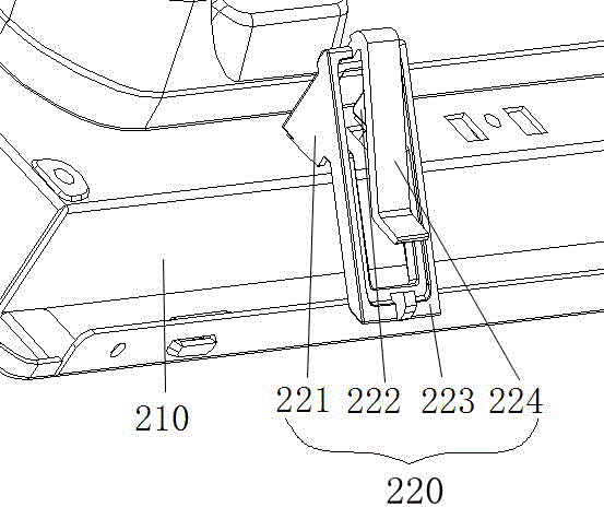
[0099] It should be noted that the Source plate support provided in Embodiment 1 of the present invention can also be transformed into other functional supports, such as a diffuser plate support.

[0100] Specifically, such as Figure 15 As shown, the diffuser plate support includes a base 710 and a support portion 720 . The base 710 is connected with the supporting part 720 as a whole, and the base 710 is used to be fixed on the backplane of the backlight module. The specific fixing method is as described in the connection method between the locking part of the backplane and the backplane in Embodiment 1, and there is no need to do too much here repeat.

[0101] The support part 720 is used to support the diffuser plate. Specifically, the diffuser plate is installed on the upper surface of the support part 720. The support part 720 is used to support the diffuser plate. The upper surface of the support part 720 and the diffuser plate are in surface contact.

[0102] In the ...

Embodiment 3

[0108] Embodiment 3 of the present invention provides a liquid crystal display device, comprising a liquid crystal display panel and the backlight module described in Embodiment 1 above. Wherein, the backlight module and the liquid crystal display panel are at opposite positions, and the liquid crystal display panel is located on the upper surface of the backlight module; the structure, function and effect of the backlight module have been described in detail in the foregoing embodiments, and will not be repeated here.


PUM


Abstract

The invention provides a backlight module, comprising a back plate, a functional board and a bracket, wherein the back plate comprises a bracket fixing hole; the bracket comprises a functional board supporting part and a back plate locking part; the functional board supporting part comprises a clamping body, a fastening buckle and a clamping groove, and the fastening buckle can be fixed in the clamping groove in a clamping way; the back plate locking part comprises a horizontal stop buckle, a back plate slide fastener and a back plate press part; the bracket can pass through the functional board supporting part, and the functional board supporting part has a limiting function for the bracket; the back plate locking part can be fixed in the bracket fixing hole; the horizontal stop buckle is used for limiting the horizontal displacement of the back plate locking part; the back plate press part is use for limiting the vertical displacement of the back plate locking part.

Description

technical field [0001] The invention relates to the field of liquid crystal television backlights, in particular to a bracket, a backlight module and a liquid crystal display device. Background technique [0002] In the prior art, some brackets are often needed as auxiliary devices during the assembly process of the backlight module, such as the source board needs to be fixed by the source board bracket, the diffuser board needs to be fixed by the diffuser bracket, etc., and the fixing structure for the bracket usually has There are two options. Among them, the first method uses screw locking to fix the bracket on the metal backplane. like figure 1 and figure 2 As shown, the backlight module includes a backplane 110 , a source board 120 , and a bracket 130 , wherein the bracket 120 includes a support portion 121 , a clamping portion 122 and a fastening portion 123 . The Source board is fixedly connected to the backplane 110 through the clamping part 122, and the fasteni...

Claims


Application Information

Patent Timeline
IPC IPC(8): G02F1/13357
Inventor 王慧马吉航
Owner HISENSE VISUAL TECH CO LTD
Why Eureka
Try Eureka