Finite element passenger restraint system model based on modularized modeling and modeling method thereof

A technology of occupant constraints and system models, applied in design optimization/simulation, special data processing applications, instruments, etc., can solve problems that affect research progress, poor flexibility, and low calculation efficiency, achieve extensive engineering application value, and improve optimization matching Efficiency, the effect of shortening the modeling time

Active Publication Date: 2017-01-04
重庆铁力士科技有限公司
View PDF3 Cites 24 Cited by
  • Summary
  • Abstract
  • Description
  • Claims
  • Application Information

AI Technical Summary

Problems solved by technology

[0003] The traditional occupant restraint system simulation analysis mainly uses the multi-rigid body madymo software developed by the Dutch Road Automotive Research Institute, and applies the multi-rigid body method for modeling and optimization. This analysis method has the characteristics of high calculation efficiency and rich dummy model database. However, it is not possible to simulate the real collision and contact between the occupant and the interior, and it is also impossible to compare the real reaction of the restraint system to absorb the kinetic energy of the dummy, which makes the simulation accuracy of the restraint system model low, and the flexibility is poor, and the matching efficiency is low.
In addition, some companies use the finite element model of the whole vehicle to study the impact of the restraint system on occupant injuries. This method avoids the shortcomings of using madymo software, but the calculation efficiency is very low, and the calculation time is greatly increased, which affects the research progress.

Method used


Image

  • Finite element passenger restraint system model based on modularized modeling and modeling method thereof
  • Finite element passenger restraint system model based on modularized modeling and modeling method thereof

Examples


Embodiment

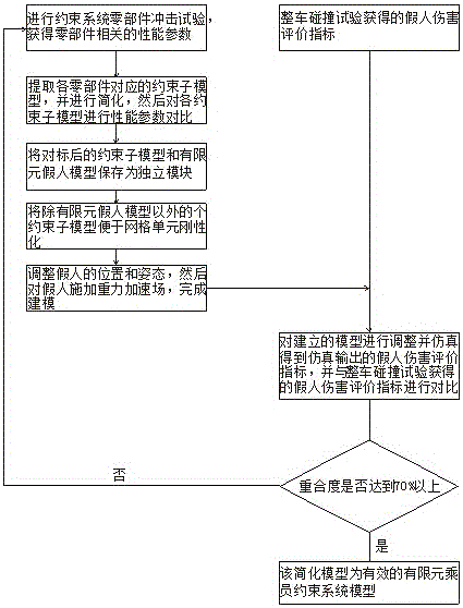
[0023] Embodiment: a finite element occupant restraint system model based on modular modeling, including the following constraint sub-models: seat belt model, airbag model, seat model, instrument panel model, steering wheel model, finite element dummy model, vehicle The floor model and the windshield model, among them, the models that have a greater impact on occupant injuries have undergone relevant performance tests to improve the reliability of each module. The performance tests include: seat belt tensile test, static airbag deployment test, seat loading dynamic test, instrument panel dynamic impact test, steering wheel static stiffness test, steering column static crushing and dynamic crushing test, TANK test and drop weight test.

[0024] see figure 1 , figure 2 , a modeling method of the above-mentioned finite element occupant restraint system model, characterized in that: comprising the following steps:

[0025] 1) According to the test specifications for the compon...


PUM


Abstract

The invention discloses a finite element passenger restraint system model based on modularized modeling. The finite element passenger restraint system model comprises a safety belt model, a safety air bag model, a seat model, an instrument board model, a steering wheel model, a finite element dummy model, a vehicle floor model and a windshield glass model. A modeling method comprises the following steps of (1) obtaining related property parameters of each component part; (2) benchmarking the property parameters of each restraint submodel; (3) respectively storing each restraint submodel and the finite element dummy model as independent modules; (4) rigidizing an edge mesh unit of each restraint submodel; (5) creating the contact between a dummy and each restraint submodel, and related control cards, so as to complete modeling; (6) properly adjusting the model established in step (5), simulating and analyzing. The finite element passenger restraint system model and the modeling method have the advantages that the modularized benchmarking and management on the restraint system simulation model can be realized, the submodels of the restraint system can be optimized and replaced, and the purpose of improving simulation accuracy and matching efficiency of the restraint system is realized.

Description

technical field [0001] The invention relates to an occupant restraint system model and a modeling method thereof, in particular to a modular modeling-based finite element occupant restraint system model and a modeling method thereof. Background technique [0002] Occupant restraint systems mainly include seat belts, airbags, seats, steering columns, instrument panels, steering wheels, floors, etc. It is mainly to avoid or reduce the secondary collision between the occupants in the vehicle and the components inside the vehicle, so as to minimize the injuries suffered by the occupants. [0003] The traditional occupant restraint system simulation analysis mainly uses the multi-rigid body madymo software developed by the Dutch Road Automotive Research Institute, and applies the multi-rigid body method for modeling and optimization. This analysis method has the characteristics of high calculation efficiency and rich dummy model database. However, it is not possible to simulate ...

Claims


Application Information

Patent Timeline
Patent Type & Authority Applications(China)
IPC IPC(8): G06F17/50
CPCG06F30/23
Inventor 潘华胡远志刘西廖高健黄杰梁锐
Owner 重庆铁力士科技有限公司
Why Eureka
Try Eureka