Cable cooling structure

A technology for cooling structures and cables, applied in the manufacture of cables/conductors, insulation of conductors/cables, circuits, etc., can solve the problems of poor cooling effect and uneven cooling degree, and achieve short cooling time, good cooling effect, and economical energy effect

Inactive Publication Date: 2017-01-04
安徽顺驰电缆股份有限公司
View PDF6 Cites 2 Cited by
  • Summary
  • Abstract
  • Description
  • Claims
  • Application Information

AI Technical Summary

Problems solved by technology

A U-shaped water tank is usually used to cool the cable. In order to prevent the water in the U-shaped water tank from overflowing, a water-blocking device is usually installed at the end of the U-shaped tank. However, in order to avoid damage to the surface of the cable caused by the water-blocking device, there It is also necessary to set a sufficiently safe gap, which causes the water in the U-shaped tank to overflow from the gap, causing the water level in the U-shaped tank to be insufficient to cover the cables, resulting in poor cooling effect and uneven cooling degree

Method used


Image

  • Cable cooling structure
  • Cable cooling structure
  • Cable cooling structure

Examples


Embodiment Construction

[0017] The following will clearly and completely describe the technical solutions in the embodiments of the present invention with reference to the accompanying drawings in the embodiments of the present invention. Obviously, the described embodiments are only some, not all, embodiments of the present invention. Based on the embodiments of the present invention, all other embodiments obtained by persons of ordinary skill in the art without making creative efforts belong to the protection scope of the present invention.

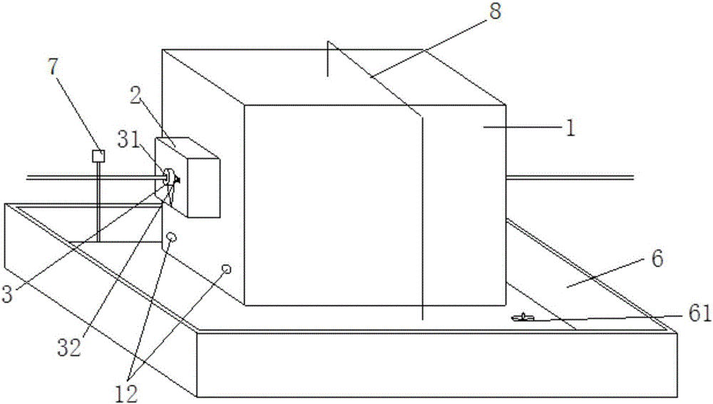
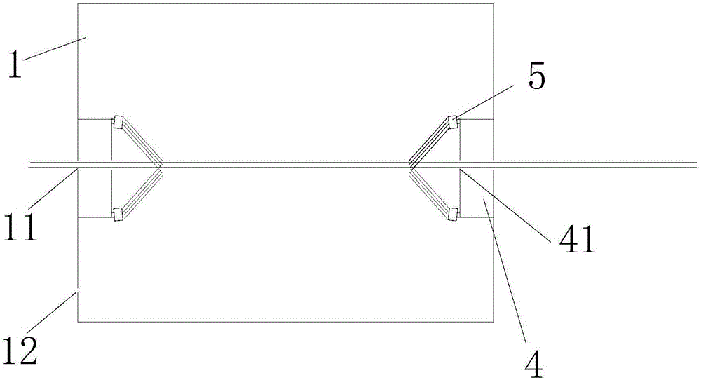
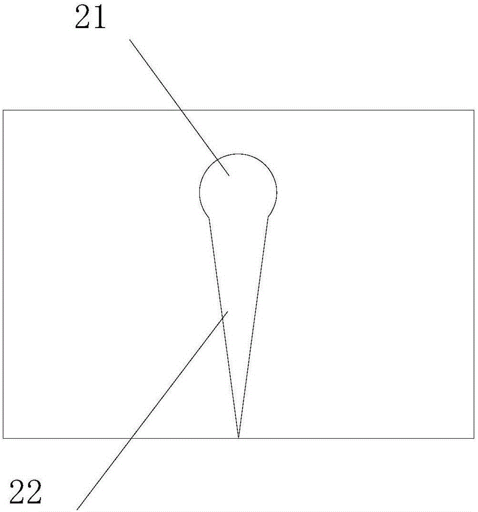
[0018] see Figure 1~3 , in an embodiment of the present invention, a cable cooling structure includes a box body 1 and a water tank 6. The box body 1 is respectively provided with an opening 11 in the middle of two parallel side walls, and the center line of the opening 11 Coincidentally, the opening 11 is circular, and the outside of the opening 11 is provided with a water retaining box 2, and the water retaining box 2 is welded and fixed on the side wall of...


PUM


Abstract

The invention discloses a cable cooling structure. The cable cooling structure comprises a box body and a water tank, wherein the box body is positioned in the water tank; openings are formed in the middle parts of two parallel side walls of the box body respectively, and center lines of the openings are overlapped; a water blocking box is arranged on the outer side of each opening; first round holes are formed in the side walls, opposite to the openings, of the water blocking boxes; V-shaped openings are formed below the first round holes; spraying devices are arranged on the inner sides of the openings and are fixedly welded on the side wall of the box body; third round holes are formed in the side walls, opposite to the openings, of the spraying devices; one nozzle is fixed on each of the upper part and the lower part of each spraying device; a sensor is arranged at the tail end of the box body; and the sensor is used for measuring the temperature of a cable and metering the length of the cable. According to the cable cooling structure, the nozzles simultaneously spray water to the cable, the surface of the whole cable can be well in contact with cooling water to perform heat exchange, the cooling effect is good, and the cooling time is short; furthermore, the quality of products is ensured, and meanwhile, water flowing into the water tank enters a water storage tank, so that the water can be recycled, and the energy source is saved.

Description

technical field [0001] The invention relates to the field of cable production, in particular to a cable cooling structure. Background technique [0002] When the cable is extruded for insulation or sheath, because the temperature is very high, it cannot be cooled immediately after the mold is released, but needs to be cooled by cooling water. In the prior art, a cable cooling water tank is usually used to cool the cable to room temperature as much as possible. A U-shaped water tank is usually used to cool the cable. In order to prevent the water in the U-shaped water tank from overflowing, a water blocking device is usually installed at the end of the U-shaped groove. Must be provided with enough safe gap again, this just makes the water in the U-shaped tank overflow from this gap, causes the water level in the U-shaped tank not enough to have not crossed cable, thereby causes poor cooling effect, and the degree of cooling is uneven. Contents of the invention [0003] Th...

Claims


Application Information

Patent Timeline
Patent Type & Authority Applications(China)
IPC IPC(8): H01B13/00H01B13/14H01B13/24
CPCH01B13/0036H01B13/145H01B13/228H01B13/24
Inventor 项志才孙成林
Owner 安徽顺驰电缆股份有限公司
Why Eureka
Try Eureka