
Assembling structure for power transformer iron core

A power transformer and assembly structure technology, applied in the field of transformers, can solve the problems of iron core temperature rise, insulation layer aging, power waste, etc., and achieve the effects of fast heat dissipation, high reliability, and compact assembly structure

Inactive Publication Date: 2017-01-04
TAIZHOU TIANLI IRONCORE MFG
View PDF0 Cites 2 Cited by
  • Summary
  • Abstract
  • Description
  • Claims
  • Application Information

AI Technical Summary

Problems solved by technology

The iron core is an important part of the transformer. It is mainly composed of the iron core and the coil. During the working process, the iron core will generate loss to convert part of the electric energy into heat energy, resulting in waste of power supply. The loss of energy will also increase the temperature of the iron core. If the iron core works at high temperature for a long time, the insulating layer on its surface will age, which will further increase the loss

Method used


Image

  • Assembling structure for power transformer iron core
  • Assembling structure for power transformer iron core
  • Assembling structure for power transformer iron core

Examples


Embodiment Construction

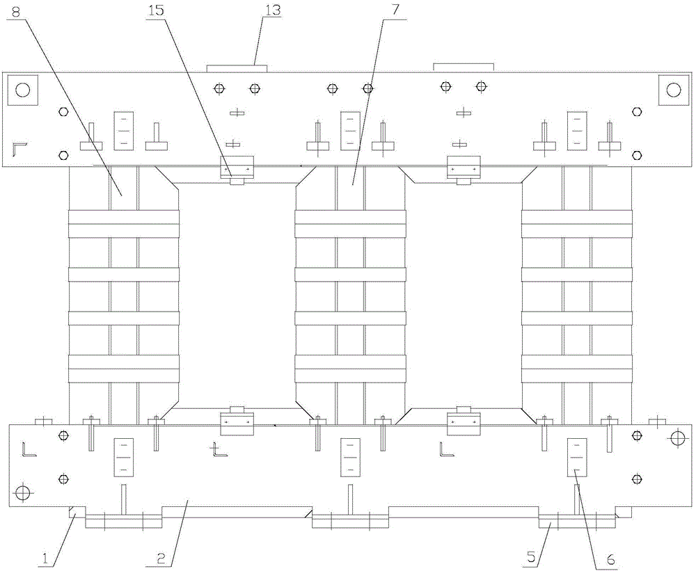
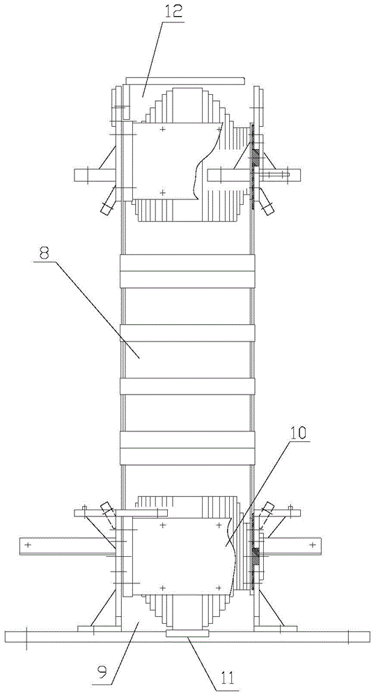
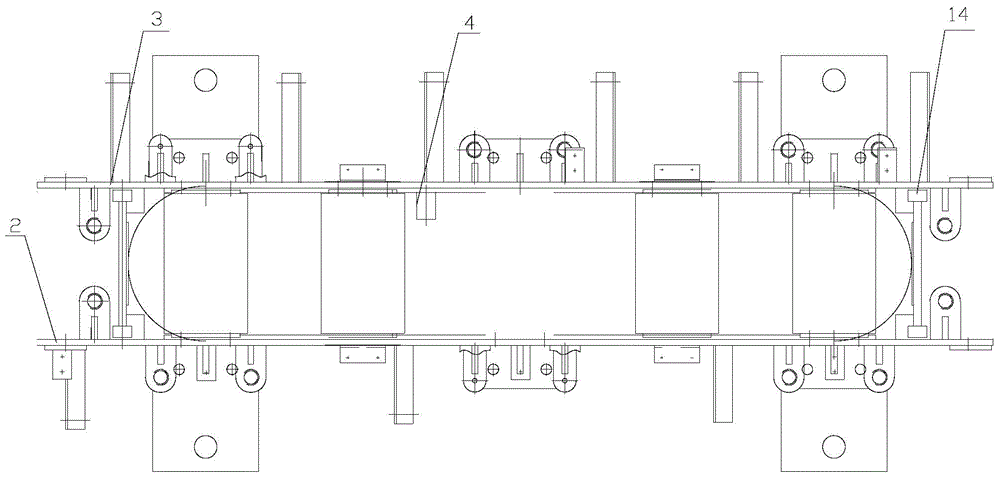
[0016] Such as figure 1 , figure 2 with image 3 As shown, the assembly structure of the power transformer iron core includes the iron core 1, the high-voltage clamp 2 and the low-voltage clamp 3 arranged on both sides of the iron core 1, and the upper end of the iron core 1 is provided with a grounding plate 4 on the side close to the low-voltage clamp 3 The lower end of the iron core 1 is provided with a foot 5, and an insulating block 11 is provided between the foot 5 and the iron core 1. A cover plate assembly 6 is provided on one side of the high-voltage clamp 2, and the cover plate assembly 6 is composed of a cover plate and a locking piece. connected to the shaft. The upper ends of the high-voltage clamp 2 and the low-voltage clamp 3 are connected and fixed by an insulating drawstring 15 .

[0017] In this embodiment, the iron core 1 has a rectangular structure, side columns 8 are arranged on both sides of the iron core 1 , and a central column 7 is arranged in the ...


PUM


Abstract

The invention relates to an assembling structure for a power transformer iron core. The assembling structure comprises an iron core and a high and lower pressure clamping members arranged on two sides of the iron core, wherein a grounding sheet is arranged on one side, where the upper end of the iron core is close to the low pressure clamping member; the lower end of the iron core is provided with a food pad; a foot pad insulating block is arranged between the foot pad and the iron core; one side of the high pressure clamping member is provided with a cover plate assembly; the high pressure clamping member is connected and fixed with the upper end of the low pressure clamping member via an insulated retractable belt; the iron core is rectangular; two sides of the iron core are provided with side columns; a middle column is disposed in the middle of the iron core; the cover plate assembly is formed by a cover plate, a lock sheet and a shaft all connected with each other; a foot pad cushion block is further placed between the iron core and the foot pad; the upper end of the iron core and one side of the low pressure clamping member are provided with a wood cushion block; side beams are arranged on the external sides of the side columns on two sides of the iron core; the upper end of the iron core is provided with an upper beam; and two sides of the upper end of the iron core are respectively provided with a paper plate. Compared with the prior art, the assembling structure for the power transformer iron core has compact structure and rational design, requires low manufacturing cost, and has great product heat radiation speed, low temperature increase, great reliability and low energy loss.

Description

technical field [0001] The invention relates to the technical field of transformers, in particular to an assembly structure of a power transformer iron core. Background technique [0002] A transformer is a power device that uses the principle of electromagnetic induction to change the AC voltage. It can play the role of voltage conversion, current conversion, impedance conversion, and voltage stabilization in the circuit. It is widely used in many fields such as power supply, machinery manufacturing, metallurgy, and railways. . The iron core is an important part of the transformer. It is mainly composed of the iron core and the coil. During the working process, the iron core will generate loss to convert part of the electric energy into heat energy, resulting in waste of power supply. The loss of energy will also increase the temperature of the iron core. If the iron core works at high temperature for a long time, the insulating layer on its surface will age, which will fu...

Claims


Application Information

Patent Timeline
Patent Type & Authority Applications(China)
IPC IPC(8): H01F27/26H01F27/24
Inventor 严桂娣
Owner TAIZHOU TIANLI IRONCORE MFG
Learn More