A heat exchange system and device for utilizing waste heat of engine exhaust gas
What is Al technical title?
Al technical title is built by PatSnap Al team. It summarizes the technical point description of the patent document.
A technology of heat exchange system and heat exchange device, which is applied to the operation mode of machines, refrigerators, adsorption machines, etc., can solve the problems of high temperature of engine exhaust waste heat, which has not been effectively used, and achieve distributed layout and effective Utilize the car space, the effect of small size
Inactive Publication Date: 2020-04-14
CENT SOUTH UNIV
View PDF16 Cites 0 Cited by
Summary
Abstract
Description
Claims
Application Information
AI Technical Summary
This helps you quickly interpret patents by identifying the three key elements:
Problems solved by technology
Method used
Benefits of technology
Problems solved by technology
[0007] The technical problem to be solved in the present invention is: for the high temperature of engine exhaust waste heat, which has not been effectively utilized so far, and with the promotion of new energy vehicles such as pure electric and hybrid vehicles, the consumption of electric energy can be reduced and the unit mileage can be effectively increased. Developing a new type of exhaust gas waste heat heat exchange system and device, which can save the energy consumption of automobiles and realize the cooling effect of vehicle air conditioners. In addition, it can also reduce the environmental pollution caused by fuel consumption.
Method used
Image
Click on the blue label to locate the original text in one second.
Reading with bidirectional positioning of images and text.
Examples
Embodiment Construction
[0027] The present invention will be described in detail below in conjunction with the accompanying drawings and embodiments, and the content of the present invention is not limited to the following embodiments.
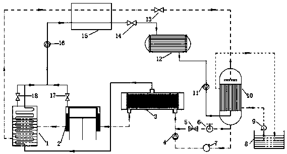
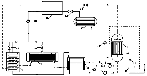
[0028] The heat exchange system and device for utilization of engine exhaust waste heat provided by the present invention, its structure is as follows figure 1 and figure 2 As shown, it includes generator one 1, generator two 2, generator three 3, first pressure controller 17, second pressure controller 18, third check valve 16, condenser 15, second pressure reducing valve 13 , throttle valve 14, evaporator 12, second one-way valve 11, absorber 10, water pump 9, water tank 8, solution pump 7, first one-way valve 4, first pressure reducing valve 5, hand valve 6, this The throttling device 14 used in the embodiment is a capillary tube with an inner diameter of 0.6-2.5mm, the condenser is a double-channel plate-fin heat exchanger, and the evaporator is a tube-fin heat...
PUM
Abstract
The invention relates to a heat exchange system and a device for utilizing waste heat of engine tail gas, belonging to the technical field of refrigeration. Aiming at the high temperature of engine exhaust waste heat, which has not been effectively utilized at present, and with the promotion of new energy vehicles such as electric vehicles and the reduction of power consumption and other application backgrounds, a new type of exhaust heat exchange system and device has been developed, specifically The difference between the two schemes, scheme 1 and scheme 2, is that the connection sequence of the three generators changes, and the structure and connection of the rest are consistent. , first pressure control valve, second pressure control valve, third one-way valve, condenser, second pressure reducing valve, throttle valve, evaporator, second one-way valve, absorber, water pump, water tank, solution pump , The first one-way valve, the first decompression valve, and the hand valve are driven by the exhaust heat of the engine exhaust, which can realize the cooling effect of the vehicle air conditioner while saving the energy consumption of the vehicle.
Description
technical field [0001] The invention relates to a device for utilizing waste heat of engine exhaust gas, in particular to a new type of absorption waste heat generator and superheater which utilizes the waste heat of engine tail gas and engine cylinder to improve the efficiency of waste heat utilization and the efficiency of waste heat utilization absorption refrigeration device systems and devices. Background technique [0002] The combustion temperature of the engine combustion chamber can be as high as 1700-2500°C, and the cylinder head, cylinder wall, and exhaust pipe that are in direct contact with the high-temperature gas need to take appropriate cooling measures, and studies have shown that the heat directly discharged with the engine exhaust pipe Accounting for more than 30% of the combustion heat, the development and utilization of its exhaust waste heat is of great significance to energy conservation and emission reduction. At the same time, the promotion and popul...
Claims
Application Information
Patent Timeline
Application Date:The date an application was filed.
Publication Date:The date a patent or application was officially published.
First Publication Date:The earliest publication date of a patent with the same application number.
Issue Date:Publication date of the patent grant document.
PCT Entry Date:The Entry date of PCT National Phase.
Estimated Expiry Date:The statutory expiry date of a patent right according to the Patent Law, and it is the longest term of protection that the patent right can achieve without the termination of the patent right due to other reasons(Term extension factor has been taken into account ).
Invalid Date:Actual expiry date is based on effective date or publication date of legal transaction data of invalid patent.