Multiple-input-multiple-output detection method and system

A detection method and detection system technology, applied in the field of communication computing, can solve problems such as high complexity and poor detection performance of MIMO detection, and achieve the effects of low complexity, excellent detection performance and improved communication rate

Inactive Publication Date: 2017-01-04
SHANGHAI RES CENT FOR WIRELESS COMM
View PDF0 Cites 1 Cited by
  • Summary
  • Abstract
  • Description
  • Claims
  • Application Information

AI Technical Summary

Problems solved by technology

[0035] In view of the shortcomings of the prior art described above, the purpose of the present invention is to provide a multiple-input multiple-output de

Method used


Image

  • Multiple-input-multiple-output detection method and system
  • Multiple-input-multiple-output detection method and system
  • Multiple-input-multiple-output detection method and system

Examples


Embodiment 1

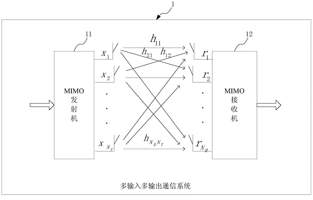
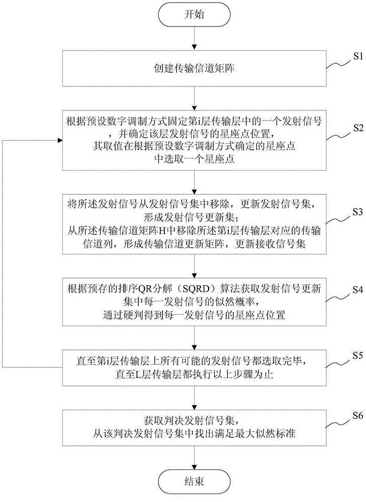
[0069] This embodiment provides a multiple-input multiple-output detection method, which is applied to a communication system including a multiple-input multiple-output transmitter 11 for sending a transmit signal and a multiple-input multiple-output receiver 12 for receiving a received signal, that is, a multiple-input multiple-output Multiple output communication system 1, such as figure 1 A schematic diagram showing the principle structure of a multiple-input multiple-output communication system, the multiple-input multiple-output transmitter has an L layer for transmitting the transmit signal sequence as S=[s 1 ,s 2 ,...,s L ] T The transmission layer of the transmitted signal, with N T transmit antennas, the MIMO receiver has N R receiving antennas, transmitting signal set Receive signal set see figure 2 , shown as a schematic flow chart of the multiple-input multiple-output detection method. Such as figure 2 As shown, the multiple-input multiple-output detec...

Embodiment 2

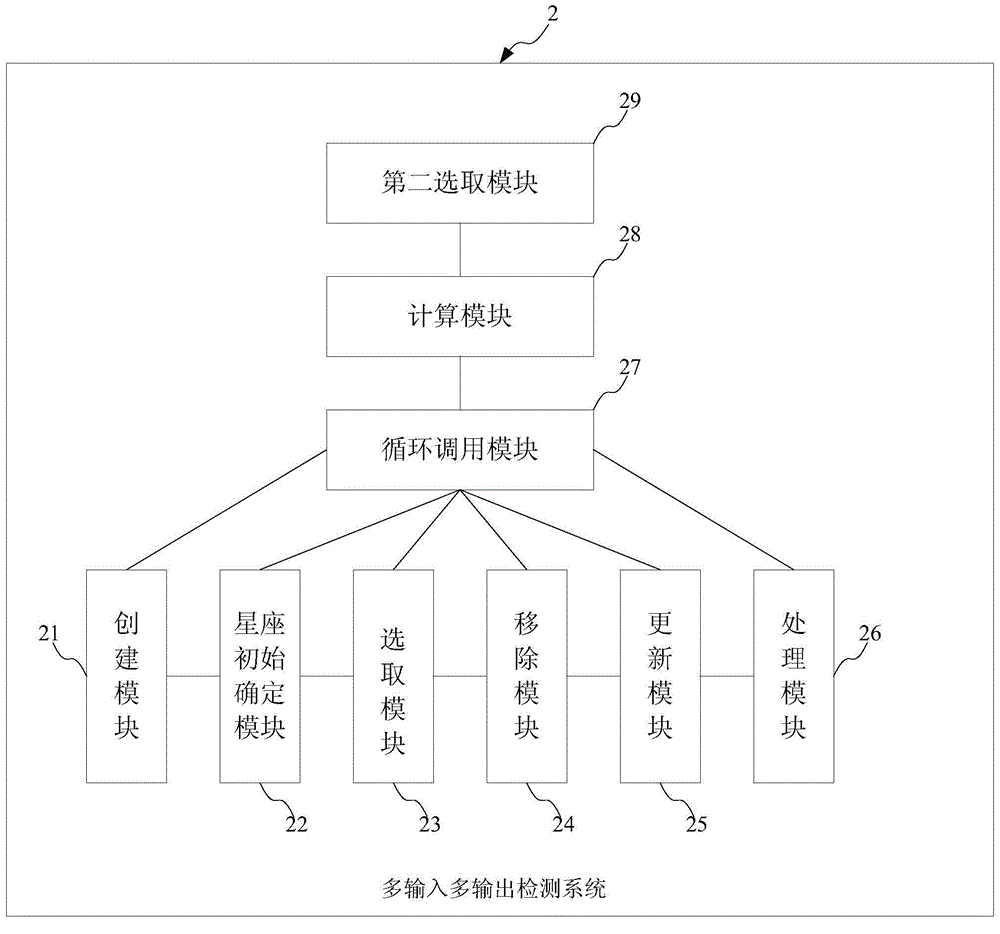
[0087] This embodiment improves a multiple-input multiple-output detection system 2, which is applied to a communication system including a multiple-input multiple-output transmitter for sending transmission signals and a multiple-input multiple-output receiver for receiving received signals. The multi-output transmitter has L layers for transmitting the transmitted signal sequence as S=[s 1 ,s 2 ,...,s L ] T The transmission layer of the transmitted signal, with N T transmit antennas, the MIMO receiver has N R receiving antennas, transmitting signal set Receive signal set see image 3 , is shown as a schematic diagram of the principle structure of the multiple-input multiple-output detection system. Such as image 3 As shown, the MIMO detection system includes: a creation module 21, a constellation initial determination module 22, a first selection module 23, a removal module 24, an update module 25, a processing module 26, a loop call module 27, and a calculation m...


PUM


Abstract

The invention provides a multiple-input-multiple-output detection method, which comprises the following steps: establishing a transmission channel matrix H; fixing one emission signal xi in the ith layer of transport layer, and selecting one constellation point in constellation points determined according to a preset digital modulation mode from the value of the emission signal; removing the emission signal xi from an emission signal set, updating the emission signal set and forming an emission signal update set X-i, and meanwhile, removing a corresponding transmission channel column and forming a transmission channel update matrix H-i, and carrying out updating and forming a received signal update set R-i; and obtaining likelihood probability of each emission signal in the emission signal update set X-i through a pre-stored sorted QR decomposition algorithm, obtaining constellation point position of each emission signal through hard decision, merging the X-i and xi to obtain a group of decision under the constellation point selected for the xi, and carrying out the steps above on all emission signals of the ith layer of transport layer and all of the transport layers to obtain a decision emission signal set, and carrying out calculating to obtain an emission signal therefrom according with the maximum likelihood standard. The multiple-input-multiple-output detection method is excellent in detection performance, and lower in complexity than an existing detection algorithm.

Description

technical field [0001] The invention belongs to the field of communication computing, in particular to the technical field of downlink MIMO detection in TDD mode in a 4G system, and in particular relates to a MIMO detection method and system. Background technique [0002] MIMO technology can generate independent parallel channels in space, realize simultaneous transmission of multi-channel data, and effectively improve the transmission rate and spectrum utilization of the system. Since the MIMO system uses multiple antennas at the transceiver end to improve the system communication rate, so The signal received by multiple receiving antennas is the superposition of signals from all transmitting antennas passing through the corresponding channel. The signals received by each receiving antenna will interfere with each other. Therefore, how to restore the original transmitting antenna signal from multiple receiving antennas became a key issue. MIMO detection technology is to us...

Claims


Application Information

Patent Timeline
IPC IPC(8): H04B7/08H04L27/34
CPCH04B7/0854H04B7/0452H04L27/3483
Inventor 朱媛桂云松王浩文
Owner SHANGHAI RES CENT FOR WIRELESS COMM
Why Eureka
Try Eureka