Imaging system positioning method and device thereof for human body scanner

A camera system and positioning method technology, applied in the field of three-dimensional scanners, can solve the problems of design position deviation, inaccurate three-dimensional coordinates, easy to cause discomfort of the human body, etc., and achieve the effect of improving accuracy

Inactive Publication Date: 2017-01-04
XIAN SUANIER ELECTRONICS TECH
View PDF4 Cites 12 Cited by
  • Summary
  • Abstract
  • Description
  • Claims
  • Application Information

AI Technical Summary

Problems solved by technology

[0002] Three-dimensional scanning is a high-tech that integrates light, machine, and charge computer technology. It is mainly used to scan the spatial shape, structure and color of objects to obtain the spatial coordinates of the object surface. Its significance lies in the ability to convert the three-dimensional information of objects Converting to digital signals that can be directly processed by the computer provides a very convenient means for the digitization of physical objects. However, traditional 3D scanning equipment is mostly contact scanners or laser scanners. The contact measurement speed is slow and the mechanical structure is complicated, which cannot meet the requirements The needs of modern measurement, and laser scanners have radiation effects on the human body, which can easily cause discomfort to the human body, which greatly limits the use of laser scanners
[0003] In order to solve the shortcomings of contact scanners and laser scanners in human body scanning, a non-contact camera scanning device is currently used for human body scanning. By taking pictures of the human body in multiple directions and processing the images, the three-dimensional coordinates of the human body can be obtained. , so as to construct a three-dimensional human body model. In this method, the accuracy of obtaining the three-dimensional coordinates of the human body determines the accuracy of the construction of the three-dimensional human body model. For the photographic scanning device, due to the installation deviation of the components, the installation of the camera is different from the design position. There is a deviation, which leads to inaccurate 3D coordinates obtained by image processing after taking pictures, which leads to inaccurate 3D modeling

Method used


Image

  • Imaging system positioning method and device thereof for human body scanner
  • Imaging system positioning method and device thereof for human body scanner
  • Imaging system positioning method and device thereof for human body scanner

Examples


Embodiment 1

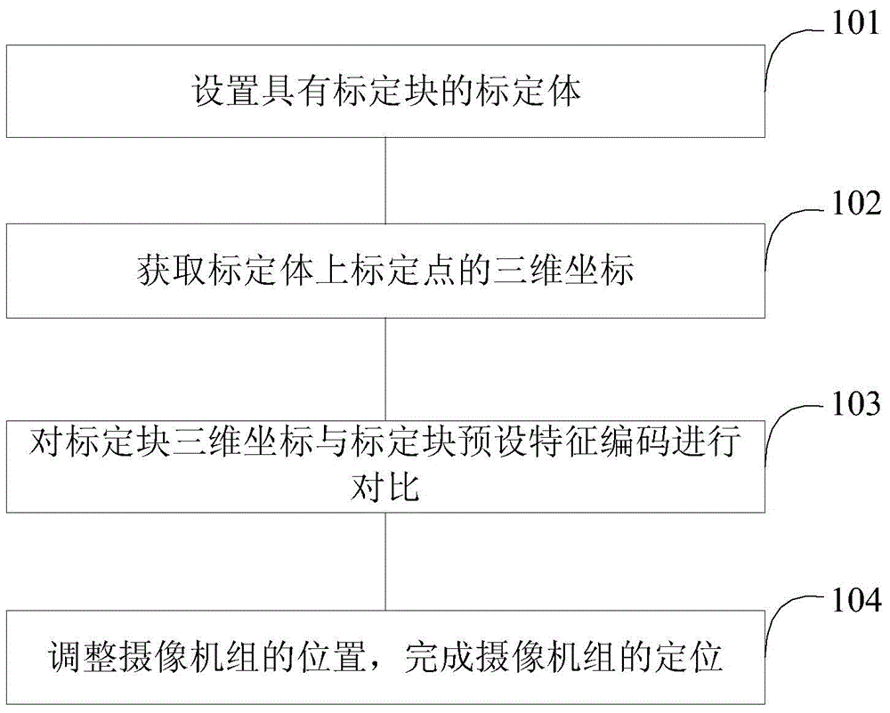
[0033] see figure 1 , is a flow chart of a camera system positioning method of a body scanner proposed by the present invention.

[0034] Such as figure 1 Shown, a camera system positioning method of a body scanner, comprising the following steps:

[0035] Step 101, setting a calibration body with a calibration block;

[0036] Wherein, in step 101, the calibration body is a three-dimensional structure with a calibration block on the surface, and the calibration block is a characteristic pattern with a feature code; the feature code is recorded when the calibration body is in the set position. The real-world three-dimensional coordinates of .

[0037] In the above step 101, the setting of the calibration body with the calibration block is specifically setting the calibration body with the calibration block at the center of the scanning device.

[0038] In the embodiment of the present invention, the calibration body can be a three-dimensional square structure, or a cylindri...

Embodiment 2

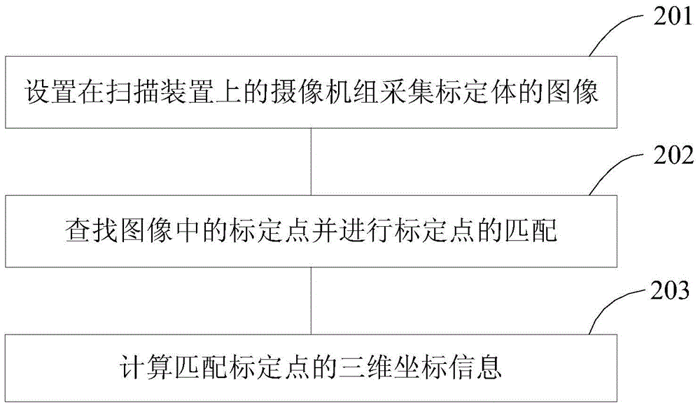
[0053] see figure 2 , is the flow chart of the method for obtaining the three-dimensional coordinates of the calibration block on the calibration body proposed by the present invention.

[0054] In Embodiment 1, the acquisition of the three-dimensional coordinates of the calibration block on the calibration body specifically includes:

[0055] Step 201, the camera group set on the scanning device collects the image of the calibration body;

[0056] In step 201, the camera group on the scanning device is a clustered camera group arranged in all directions at 360 degrees, the calibration body is set at the center of the scanning device, and the clustered camera group performs omnidirectional image acquisition on the calibration body.

[0057] Step 202, searching for the calibration blocks in the image and matching the calibration blocks;

[0058] In step 202, search and extract the marked blocks from the images collected by the camera group, and match the marked blocks.

[0...

Embodiment 3

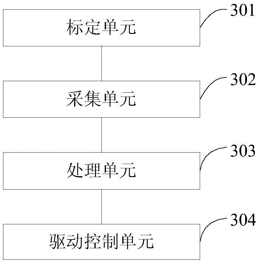
[0064] see image 3 , is a structural diagram of a camera system positioning device of a body scanner proposed by the present invention.

[0065] A positioning device of a camera system of a body scanner, comprising:

[0066] A calibration unit 301, configured to provide calibration reference information;

[0067] An acquisition unit 302, configured to acquire a calibration volume image having a calibration block;

[0068] The processing unit 303 extracts and matches the calibration blocks from the calibration volume image collected by the acquisition unit, calculates the three-dimensional coordinates of the calibration blocks, and compares the three-dimensional coordinates with the preset three-dimensional coordinate values ​​corresponding to the feature codes of the calibration blocks, Generate control commands for the camera group;

[0069] The drive control unit 304 receives a control command from the processing unit to the camera group, and controls the controller of t...


PUM


Abstract

The present invention discloses an imaging system positioning method for a human body scanner. The method comprises the steps of setting a calibration body provided with a calibration block; obtaining the three-dimensional coordinates of the calibration block on the calibration body; comparing the three-dimensional coordinates of the calibration block with the preset feature encoding of the calibration block; adjusting the position of a camera set to complete the positioning of the camera set. The present invention also discloses an imaging system positioning device for the human body scanner. According to the technical scheme of the invention, the camera set of the human body scanner is adjusted through setting the calibration body, so that the shooting angle and the shooting distance of the camera set are at preset positions. Therefore, the accuracy of the human body scanning process is improved.

Description

technical field [0001] The invention relates to a three-dimensional scanner technology, in particular to a positioning method and device for a camera system of a human body scanner. Background technique [0002] Three-dimensional scanning is a high-tech that integrates light, machine, and charge computer technology. It is mainly used to scan the spatial shape, structure and color of objects to obtain the spatial coordinates of the object's surface. Its significance lies in the ability to convert the three-dimensional information of objects Converting to digital signals that can be directly processed by the computer provides a very convenient means for the digitization of physical objects. However, traditional 3D scanning equipment is mostly contact scanners or laser scanners. The contact measurement speed is slow and the mechanical structure is complex, which cannot meet the requirements The needs of modern measurement, and laser scanners have radiation effects on the human ...

Claims


Application Information

Patent Timeline
Patent Type & Authority Applications(China)
IPC IPC(8): H04N5/232G06T7/00
Inventor 杨少毅褚智威
Owner XIAN SUANIER ELECTRONICS TECH
Why Eureka
Try Eureka