Camera module based on camera lens tilt controllable motor and quick focusing sensor, and control method

A camera module and sensor technology, applied in image communication, color TV parts, TV system parts and other directions, can solve the problems of difficult to popularize application, simultaneous application of phase detection sensors, difficult optical image stabilization, etc. Achieve the effect of improving user experience, simplifying back-end debugging and correction technology and process requirements, and improving production yield

Inactive Publication Date: 2017-01-04
DONGGUAN PRECISION PHOTONICS LTD
View PDF6 Cites 28 Cited by
  • Summary
  • Abstract
  • Description
  • Claims
  • Application Information

AI Technical Summary

Problems solved by technology

Investigating the difficulties in these aspects, it is extremely challenging in terms of the production yield of PDAF cameras, production automation equipment requirements (that is, production costs), and back-end debugging and correction technologies and methods (that is, new process capabilities and production efficiency). making it difficult to popularize the application
[0005] Since the deflection of the lens will affect the phase detection signal of the phase detection image sensor, it is difficult to apply the optical image stabilization and the phase detection sensor to the smartphone camera module at the same time

Method used


Image

  • Camera module based on camera lens tilt controllable motor and quick focusing sensor, and control method
  • Camera module based on camera lens tilt controllable motor and quick focusing sensor, and control method
  • Camera module based on camera lens tilt controllable motor and quick focusing sensor, and control method

Examples


Embodiment Construction

[0035] The structure and method of the present invention will be further described below in conjunction with the accompanying drawings and preferred specific embodiments of the present invention.

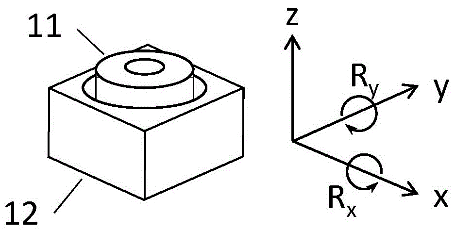
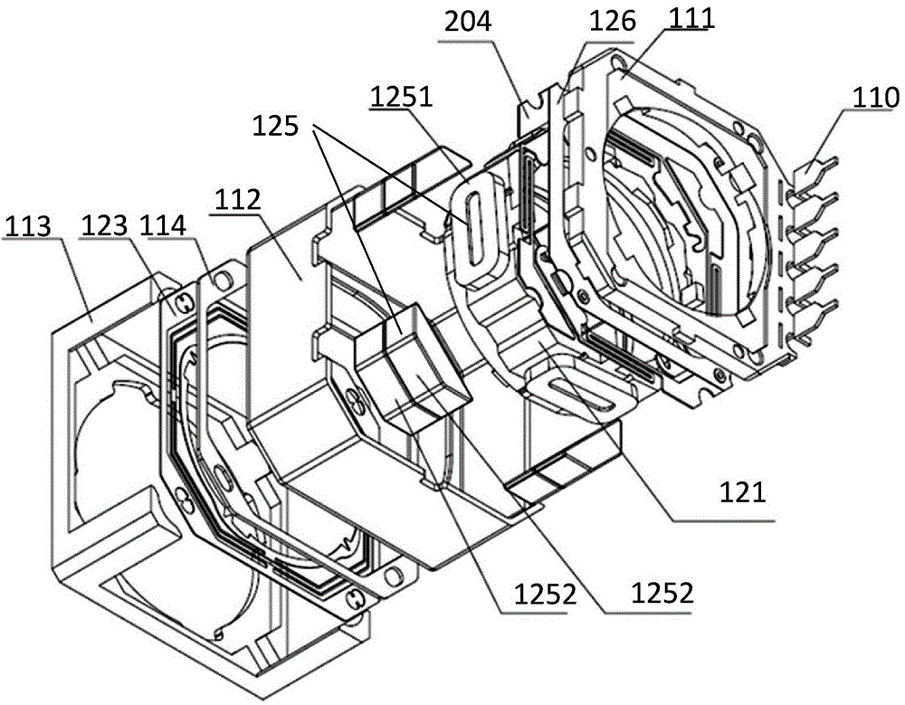
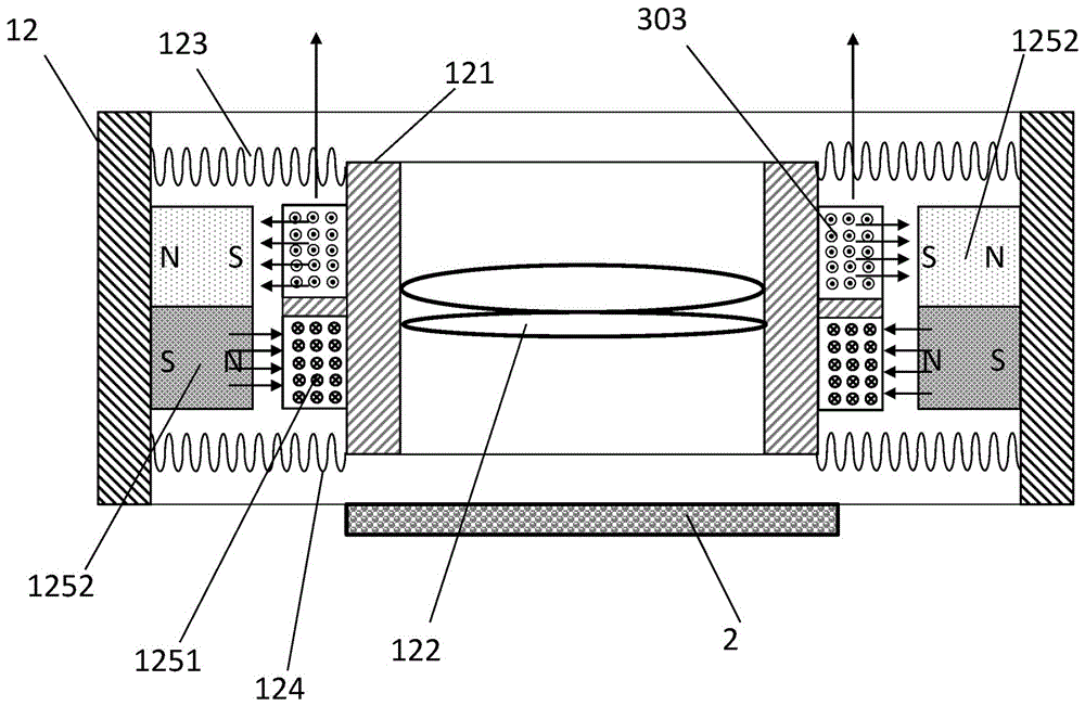
[0036] refer to Figure 1 to Figure 8As shown in , the present invention is based on a camera module with a lens tilt controllable motor and a fast focus sensor, including a focus motor 1 and a phase autofocus image sensor 2 located at the bottom of the focus motor 1 . For the convenience of description, the axis perpendicular to the phase AF image sensor is the Z axis, the X and Y directions perpendicular to the axis are the X axis and the Y axis, and the plane formed by the X axis and the Y axis is parallel to the phase AF image. The light-receiving surface of the sensor. The focus motor 1 of the present invention is used to drive the optical imaging lens component to move in parallel along the Z-axis, or tilt and off-axis around the X-axis, or tilt and off-axis around the Y axis...


PUM


Abstract

The invention provides a camera module based on a camera lens tilt controllable motor and a quick focusing sensor, and a control method, relates to the technical field of micro-camera modules, and solves the problem of camera lens initial mounting position error or additional parasitic deflection generated in the camera lens moving process required by auto-focusing and after movement. The camera module comprises a focusing motor and a phase auto-focusing image sensor, wherein the focusing motor comprises a motor stator and a motor rotor arranged in the motor stator; the motor stator comprises a camera lens mount; more than three groups of electromagnetic drivers which are used for driving a camera lens part to do parallel movement vertical to the axis of the phase auto-focusing image sensor and do tilt deflection motion vertical to the X direction and the Y direction of the axis, are arranged between the outside wall of the camera lens mount and the inner wall of the motor stator. The production automation equipment requirement of a PDAF (phase detection auto focus) camera can be reduced, and a back-end adjusting and correcting technology and a process requirement are simplified, so that production yield is increased and the production cost is reduced.

Description

technical field [0001] The invention relates to the technical field of miniature camera modules, in particular to the structure and control method of high-pixel and highly integrated camera modules used in smart phones. Background technique [0002] The increasing popularity of high-pixel and highly integrated cameras in smartphones has made the quality of photos taken by mobile phones approach or even surpass that of ordinary digital cameras. For ordinary digital cameras, due to their large size and space, more complex optical paths, sensors and drive mechanisms can be allowed, so that optical anti-shake structures and phase detection sensors can be set to achieve optical anti-shake and phase detection fast autofocus functions. But high-pixel mobile phone cameras do not contain some optical and mechanical components of ordinary digital cameras. This lack of hardware will undoubtedly make the camera phone's camera effect worse than that of a digital camera, and the focusing...

Claims


Application Information

Patent Timeline
Patent Type & Authority Applications(China)
IPC IPC(8): H04N5/232
CPCH04N23/66H04N23/67H04N23/68
Inventor 洪航庆刘志远肖顺利麦练智
Owner DONGGUAN PRECISION PHOTONICS LTD
Why Eureka
Try Eureka