Loudspeaker for reducing vibration wave of vibrating diaphragm

A loudspeaker and vibration technology, applied in the direction of sensors, electrical components, etc., can solve problems such as large-amplitude bad residual vibration, improved speaker design, and affecting the sound quality of the speaker, so as to reduce the generation of residual vibration and improve the sound quality.

Inactive Publication Date: 2017-01-04
宋行智
View PDF6 Cites 1 Cited by
  • Summary
  • Abstract
  • Description
  • Claims
  • Application Information

AI Technical Summary

Problems solved by technology

However, this design produces large amplitudes and undesirable aftershocks at certain frequencies, see Figure 14 , is the time (ms)-decibel (dB)-frequency (Hz) test graph obtained by the inventor's test of the known loudspeaker diaphragm. It can be seen from this figure that when the known suspension edge is used, the known loudspeaker vibration The membrane will produce large vibration waves and bad after-vibration at certain frequencies. For example, at one kilohertz (Hz), a large amount of noise will be generated, which will seriously affect the sound quality of the speaker. Therefore, how to design a speaker that can truly eliminate after-vibration waves has always been is one of the challenges that the industry is trying to overcome
[0005] In order to achieve the purpose of reducing the vibration wave, it is an excellent way to improve the efficiency of the design of the hanging edge. However, looking at the current known technologies and various books, the current circulating speakers have not been designed for the hanging edge. It is a pity to improve, the inventor proposes the structural design of the present invention in view of this

Method used


Image

  • Loudspeaker for reducing vibration wave of vibrating diaphragm
  • Loudspeaker for reducing vibration wave of vibrating diaphragm
  • Loudspeaker for reducing vibration wave of vibrating diaphragm

Examples


Embodiment Construction

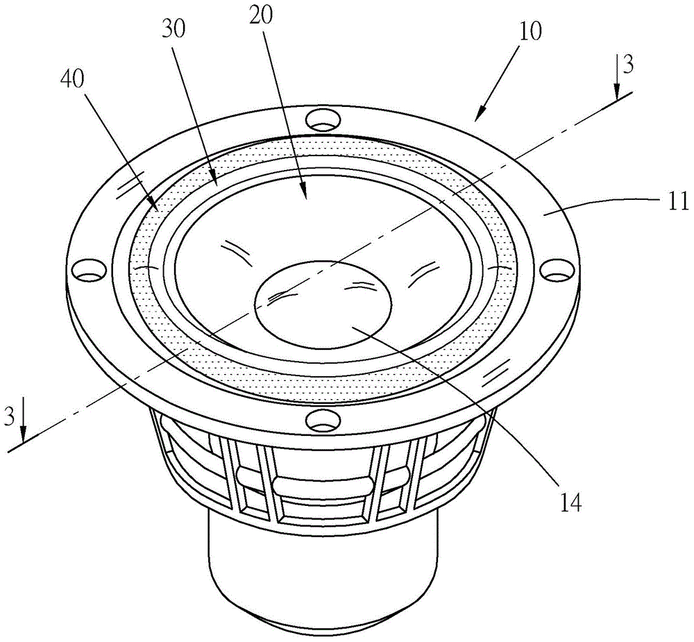
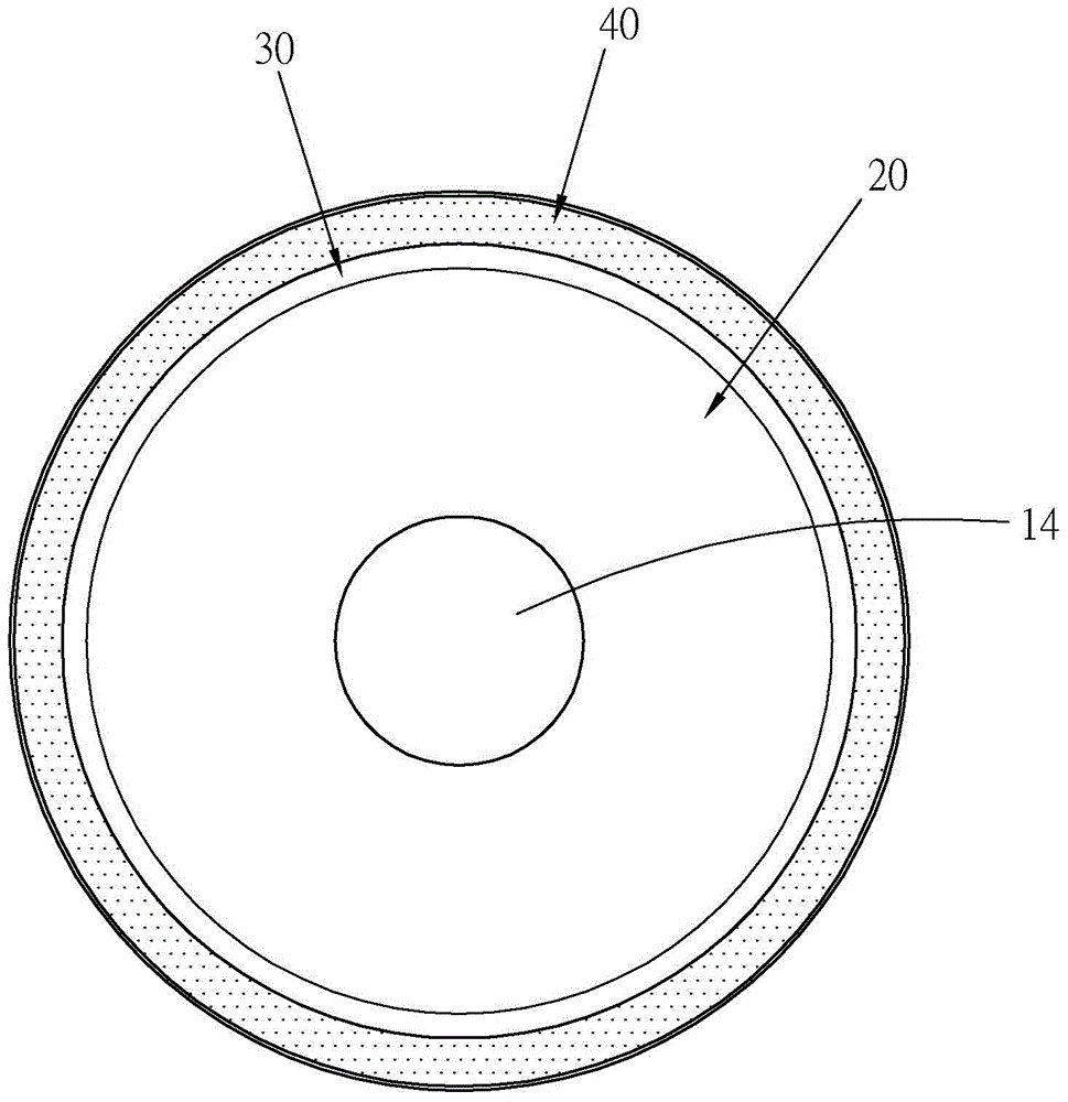
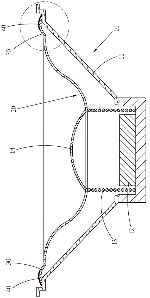
[0038] see Figure 1 to Figure 4 , is the speaker 10 for reducing the diaphragm vibration wave provided by the first preferred embodiment of the present invention, which has a diaphragm 20 installed in the speaker 10, and the diaphragm 20 and the speaker 10 are connected by a hanging edge 30.

[0039] The vibrating membrane 20 is a cone-shaped thin object, which is flexible and can be made of materials such as metal, polymer material, paper or fiber (carbon fiber or glass fiber).

[0040] In detail, the loudspeaker 10 has a frame 11 , a magnetic component, a hanging edge 30 , a diaphragm 20 and a dustproof cover 14 . The magnetic assembly is installed between the frame 11 and the vibrating membrane 20 , and includes a magnet 12 and a coil 13 to generate magnetic forces that attract or repel each other to push the vibrating membrane 20 to move in the axial direction of the coil 13 . The hanging edge 30 is ring-shaped, its outer periphery is connected to the frame 11 , and its ...


PUM


Abstract

The invention provides a loudspeaker for reducing the vibration wave of a vibrating diaphragm. The loudspeaker comprises a framework, a flexible vibrating diaphragm in the form of a thin-shaped object arranged on the framework, a flexible suspension edge made of the same material with that of the vibrating diaphragm or different materials from those of the vibrating diaphragm, and at least one damping material layer made of high-damping and low-elastic-modulus materials. The inner peripheral edge of the suspension edge is connected to the vibrating diaphragm, and the outer peripheral edge of the suspension edge is connected to the framework. The damping material layer is arranged along the periphery of the suspension edge and is attached to at least one surface of the suspension edge. The inner side edge of the damping material layer is kept at a certain spacing from the inner periphery of the suspension edge. The damping material layer is attached to at least one surface of the suspension edge in the mass symmetric manner. According to the invention, at least one surface of the suspension edge of the vibrating diaphragm is provided with the damping material layer, so that the vibration energy transmitted to the suspension edge can be eliminated. Meanwhile, the generation of residual vibration waves is reduced, and the sound quality of the loudspeaker is improved.

Description

technical field [0001] The present invention relates to a loudspeaker device, in particular to a loudspeaker which utilizes damping material to reduce the vibration wave of the diaphragm and adjust the vibration deformation, so as to achieve ideal deformation and damping. Background technique [0002] Press, a speaker is a device that converts electrical energy into sound. The structure of the loudspeaker has a frame, a magnetic component, a diaphragm and a hanging edge, etc. The hanging edge connects the diaphragm and the frame, so that the diaphragm can vibrate on the frame, and the magnetic force generated by the magnetic component pushes the diaphragm to produce sound . [0003] When the diaphragm vibrates, the generated vibration wave travels outward along the diaphragm to the suspension edge. However, it is difficult for most speakers to properly match the impedance of the suspension edge and the diaphragm. When the vibration wave travels to the suspension edge, it is...

Claims


Application Information

Patent Timeline
Patent Type & Authority Applications(China)
IPC IPC(8): H04R9/06
Inventor 宋行智
Owner 宋行智
Why Eureka
Try Eureka