A material-saving stamping die and its coiling device

A stamping die and coil material technology, which is applied in the field of material-saving stamping die and its coil device, can solve the problems of low material utilization rate of stamping parts, one more process, and increased cost, so as to improve utilization rate, reduce cost, cost-saving effect

Active Publication Date: 2018-09-07
今朝联合有限公司
View PDF6 Cites 0 Cited by
  • Summary
  • Abstract
  • Description
  • Claims
  • Application Information

AI Technical Summary

Problems solved by technology

[0003] The purpose of the present invention is to address the shortcomings of the prior art, overcome the problem that the material utilization rate of stamping parts in the prior art is not high, and after the material utilization rate is improved, there is one more process for winding materials, which consumes man-hours and increases costs, and provides A material-saving stamping die and its coiling device

Method used


Image

  • A material-saving stamping die and its coiling device
  • A material-saving stamping die and its coiling device
  • A material-saving stamping die and its coiling device

Examples


Embodiment

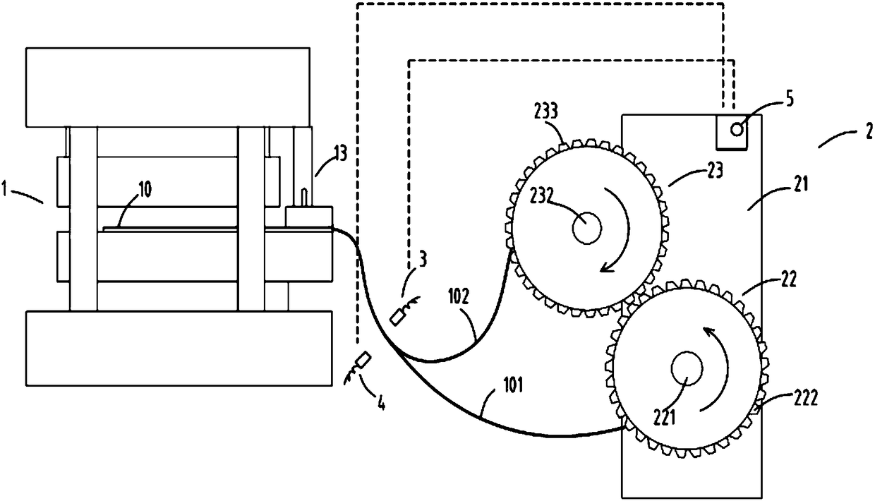
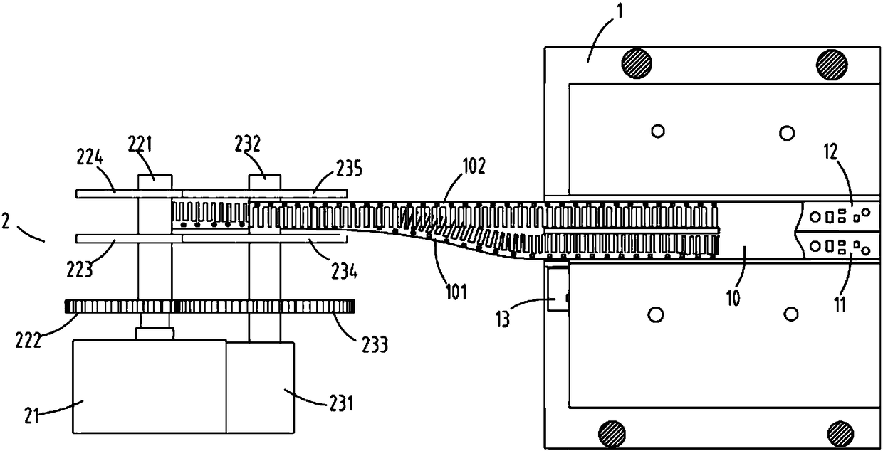
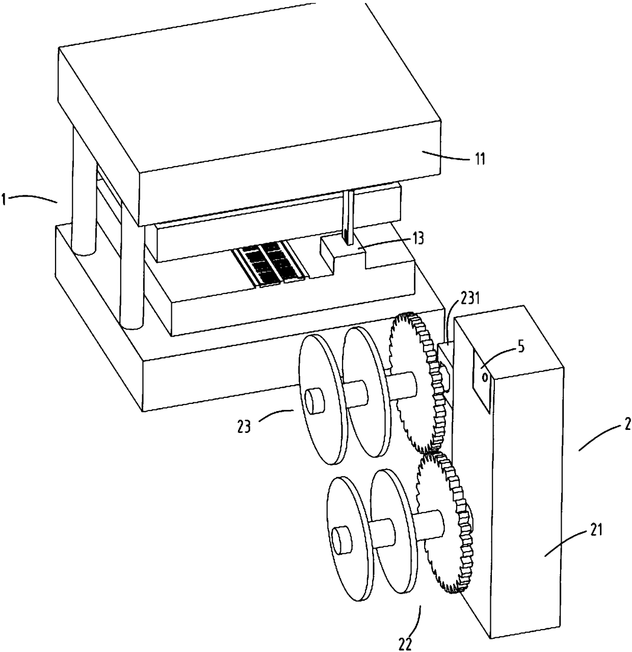
[0030] figure 1 It is a schematic diagram of the front view of the material-saving stamping die and its coiling device, figure 2 It is a top view schematic diagram of the material-saving stamping die and its coiling device, image 3 It is a partial three-dimensional schematic diagram of the material-saving stamping die and its coiling device, Figure 4 It is a schematic diagram of the drawing device of the material-saving stamping die and its coiling device, Figure 5 It is a schematic diagram of the transmission block and hooking part of the pulling device, Image 6 It is the internal schematic diagram of the hooking part of the pulling device, Figure 7 It is the base, guide seat and mounting seat of the pulling device. Such as figure 1 , figure 2 , image 3 , Figure 4 , Figure 5 , Image 6 with Figure 7As shown, what is provided in this embodiment is a material-saving stamping die and its coiling device, including a stamping die part 1 and a coiling part 2; ...


PUM


Abstract

The invention relates to a material-saving punching die and material winding device. The material-saving punching die and material winding device comprise a punching die part and a material winding part, wherein the punching die part comprises a punching die a, a punching die b and a material pulling device; the punching die a and the punching die b are arranged in a mirror-symmetric manner; through synchronous working of the punching die a and the punching die b, a finished material strip a and a finished material strip b which are mirror-symmetric are punched out from a single material strip; the material winding part comprises a machine case, a driving material winding device and a driven material winding device; the driven material winding device is driven by the driving material winding device to rotate; the rotating speed of the driving material winding device is the same as that of the driven material winding device; and the rotating direction of the driving material winding device is opposite to that of the driven material winding device. By adoption of the material-saving punching die and material winding device, the problems that in the prior art, the utilization ratio of punching part materials is not high, the working procedure of material winding is added after the material utilization ratio is increased, and then more time is consumed and the cost is increased can be solved.

Description

technical field [0001] The invention relates to the field of stamping equipment, in particular to a material-saving stamping die and a coiling device thereof. Background technique [0002] Steel materials account for more than 70% of the cost of stamping parts. Improving the utilization rate of raw materials is of great significance to reducing the cost of stamping parts and improving product competitiveness. In the prior art, in order to improve the utilization rate of materials, the original one out of one mold is changed into one of two, and the two sets of molds form a mirror image and are arranged alternately. Bringing the spaced part of the raw material between the two parts achieves the effect of improving the utilization rate of the raw material. However, due to the staggered setting of the mirror image, the two finished product tapes come out with one front and one reverse, and a positive side will appear when the coiling device is coiling the material. On the othe...

Claims


Application Information

Patent Timeline
Patent Type & Authority Patents(China)
IPC IPC(8): B21D22/02B21C47/04
CPCB21C47/04B21D22/02
Inventor 厉海飞
Owner 今朝联合有限公司
Why Eureka
Try Eureka