3D printing method for adding reinforcement-ratio based directional fibers into binding materials

A cementitious material and 3D printing technology, applied in the direction of additive processing, ceramic molding machine, manufacturing tools, etc., can solve the problems of molding time, low strength, unfavorable force of concrete structure, etc., and achieve the effect of reducing changes

Active Publication Date: 2017-01-11
TONGJI UNIV
View PDF8 Cites 38 Cited by
  • Summary
  • Abstract
  • Description
  • Claims
  • Application Information

AI Technical Summary

Problems solved by technology

However, for other substrates with low strength after molding and special stress requirements after molding, such as gypsum, cement, etc., the formed structure is easy to crack due to use or stress, so the performance cannot be guaranteed.
[0003] Taking concrete as an example, the current 3D concrete printing is a single concrete material. There are problems: first, only fine granular materials can be used as printing and forming raw materials, so only thinner layers can be used to build components, which is difficult Add steel bars to the concrete; secondly, at the same time, due to the molding time problem of existing concrete materials, there is always a wavy surface on the surface; due to different molding times between layers, there are adhesion defects between layers, resulting in the printed concrete structure Unfavorable force
[0004] Of course, if combined with metal powder fusion welding technology, it is also feasible to construct the steel skeleton during the concrete printing process, but its technical difficulty and economic cost are completely unacceptable

Method used


Image

  • 3D printing method for adding reinforcement-ratio based directional fibers into binding materials
  • 3D printing method for adding reinforcement-ratio based directional fibers into binding materials
  • 3D printing method for adding reinforcement-ratio based directional fibers into binding materials

Examples


Embodiment 1

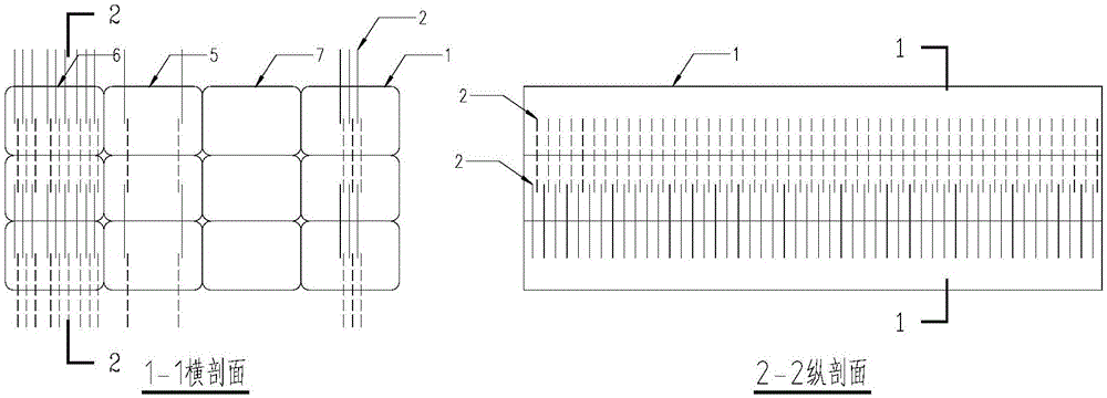
[0044] The 3D printing implementation method of increasing the directional fiber based on the reinforcement ratio in the cementitious material is characterized in that it includes the following steps:

[0045] Step 1, using double print head 3D printer technology (this technology already belongs to the prior art), to realize the lamellar layer printing of normal concrete by one of the print heads;

[0046] Step 2. When printing reaches the position where the steel bars need to be arranged, according to the required amount of fibers, another print head prints steel fibers perpendicular to the concrete printing surface;

[0047] Step 3. Insert the steel fiber into the printed concrete, and keep part of the length outside the layer;

[0048] Step 4. When printing the next layer of concrete, the above-mentioned exposed fiber part is covered by the newly printed concrete, and overlaps with the subsequent printed fibers in the length direction to ensure the transmission of the bondi...

Embodiment 2

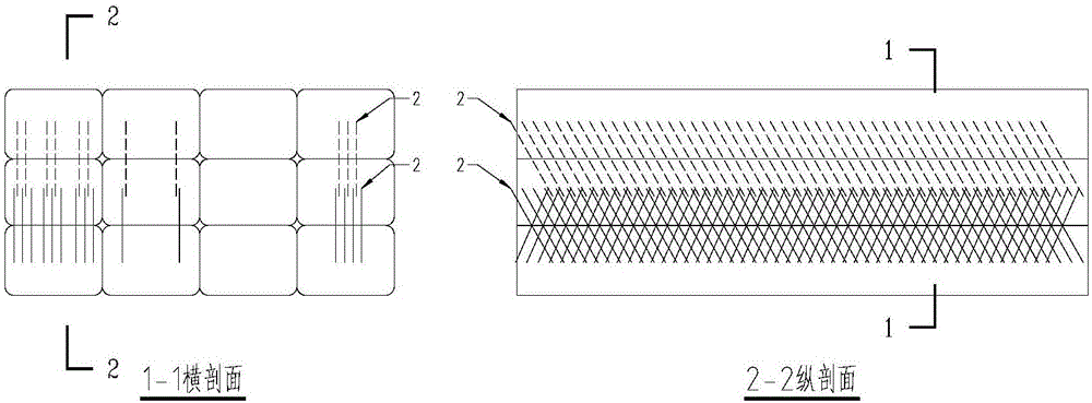
[0053]Step 1. Use multiple print heads to realize that one of the print heads prints the flake layer of normal concrete (this technology can also be realized through existing existing technologies), and the other print heads print fibers;

[0054] Step 2. When printing to the position where the steel bars need to be arranged, according to the converted fiber amount, direction and position, different print heads insert fibers into the printed concrete in a specific direction;

[0055] Step 3: insert the fiber into the printed concrete, and keep part of the length outside the layer;

[0056] Step 4. When printing the next layer of concrete, the direction of travel of the printing head should be opposite to that of the obliquely arranged fiber sets to avoid changing the direction of the fibers. The above-mentioned exposed fiber part is covered by the newly printed concrete, and overlaps with the subsequent printed fiber in the length direction to ensure the transmission of the bo...

Embodiment 3

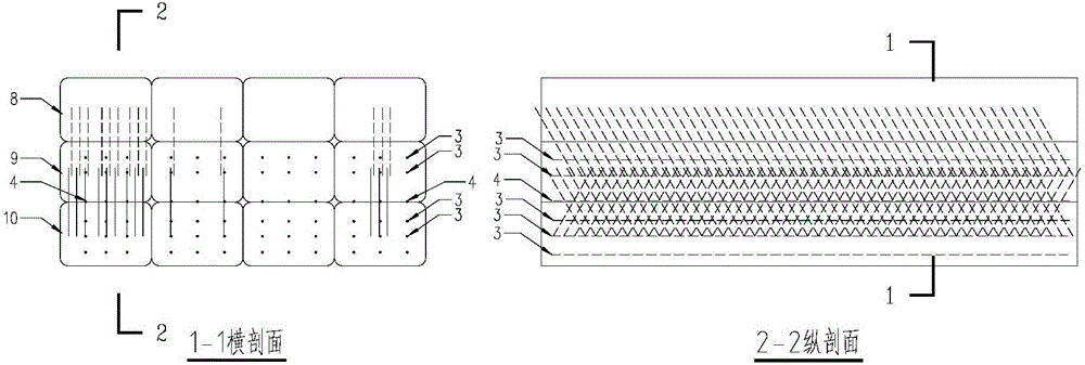
[0061] Step 1. Use multiple print heads to realize that one of the print heads prints the flake layer of normal concrete, and the other print heads print fibers;

[0062] Step 2. If the amount of concrete extruded during printing is small, horizontal fiber printing can be arranged between layers; the most favorable way is to print horizontal fibers directly inside the concrete extrusion. This requires synchronous extrusion of horizontal continuous fibers in the direction of travel of the printing head when concrete is extruded, or even continuous iron wire.

[0063] Step 3. The fibers to be arranged are inserted into the printed concrete in a specific direction by the same print head according to the required arrangement position, according to the converted fiber amount, direction and position.

[0064] Step 4. The fiber is inserted into the printed concrete, and part of the length is reserved outside the layer.

[0065] Step 5. When printing the next layer of concrete, the r...


PUM


Abstract

The invention discloses a 3D printing method for adding reinforcement-ratio based directional fibers into binding materials. The technical idea of the invention is to convert the amount of the corresponding cross-section steel bars into the corresponding amount of the drawn fibers, and according to the direction and position of the reinforcing bar arrangement, and to arrange the reinforcing bars in the fixed direction, fixed quantity and position. The 3D printing method comprises, step 1, using the 3D printer technology with two printing heads, one of which is to print normal concrete layer by layer; step 2, when in the reinforcing bar position to be printed, using the other printing head to print steel fibers by being perpendicular to the concrete according to the needed fiber amount; step 3, inserting the steel fibers into the printed concrete and reserving a part of length outside the layers; step 4, when to print the next layer of concrete, covering the exposed fibers with the reprinted concrete, and having the fibers printed later overlapped in the length direction so as to ensure the transmission of bond anchor force; and others.

Description

technical field [0001] The invention relates to a technical improvement method using cementitious materials such as gypsum or concrete as a printing base material to improve the quality of 3D printing. Background technique [0002] Existing 3D printing is basically based on the same material or materials mixed with the same composition, without considering the combined printing of multiple materials. This has no disadvantages for the existing additive manufacturing molding such as resin or metal powder, because of its high strength after molding. However, for other substrates with low strength after molding and special stress requirements after molding, such as gypsum, cement, etc., the formed structure is easy to crack due to use or stress, so the performance cannot be guaranteed. [0003] Taking concrete as an example, the current 3D concrete printing is a single concrete material. There are problems: first, only fine granular materials can be used as printing and forming...

Claims


Application Information

Patent Timeline
Patent Type & Authority Applications(China)
IPC IPC(8): B28B1/00B28B1/52B33Y10/00B33Y70/00B33Y80/00
CPCB28B1/001B28B1/523B33Y10/00B33Y70/00B33Y80/00
Inventor 李方元
Owner TONGJI UNIV
Why Eureka
Try Eureka