Mold of prefabricated exhaust passage

A technology for exhaust ducts and molds, which is applied to molds, manufacturing tools, mold auxiliary parts, etc., can solve the problems of laborious mandrel frame retraction, time-consuming removal of inner mold frames, and wear of parts, so as to improve production efficiency and production. Quality, improve work efficiency, enhance the effect of service life

Active Publication Date: 2017-01-11
魏张木
View PDF4 Cites 12 Cited by
  • Summary
  • Abstract
  • Description
  • Claims
  • Application Information

AI Technical Summary

Problems solved by technology

[0002] Usually, the molds for residential exhaust ducts basically only have outer molds, but lack inner molds. The inner molds are made by manual operation. Due to the manual operation site occupying a lot of space, the waste of raw materials is serious, and the wall thickness of the exhaust duct is uneven. Due to the different technical proficiency of workers and specific operations, it is difficult to achieve standardized production of the exhaust duct, and the problem of uneven thickness of the exhaust duct is prone to occur, and the impact force of the collision cannot meet the design requirements. Manufacturers bring great difficulties and production pressure
[0003] In order to solve the above problems, Chinese patent CN101462300B disclosed a prefabricated thin-wall exhaust duct forming mold on June 24, 2009. The patent utilizes the outer mold, inner mold and cavity design to realize the mechanized operation of the exhaust duct. It solves the problems of difficult molding of the overall mold and inconvenient disassembly of the mold core, and improves the production efficiency and production quality
However, the use of inner gussets in the inner corners of the inner mold frame of the disclosed patent will cause other parts of the inner wall to be damaged due to shrinkage and bending, which will lead to uneven inner walls of the flue gas duct produced, and the weight does not meet the specifications, and it is also very easy to cause slurry leakage. It is often necessary to replace the inner mold frame; the structure of the central rod of the mandrel frame retractable mechanism is complex, there are many parts, the assembly procedure is complicated, and the tie rod cannot be directly connected with the rear central rod, and when in use, the adjusting screw cannot directly drive the rear central rod The front and rear movement of the core mold frame is very laborious, which is easy to cause wear of the parts, and will also make it more time-consuming to take out the inner mold frame

Method used


Image

  • Mold of prefabricated exhaust passage
  • Mold of prefabricated exhaust passage
  • Mold of prefabricated exhaust passage

Examples


Embodiment 1

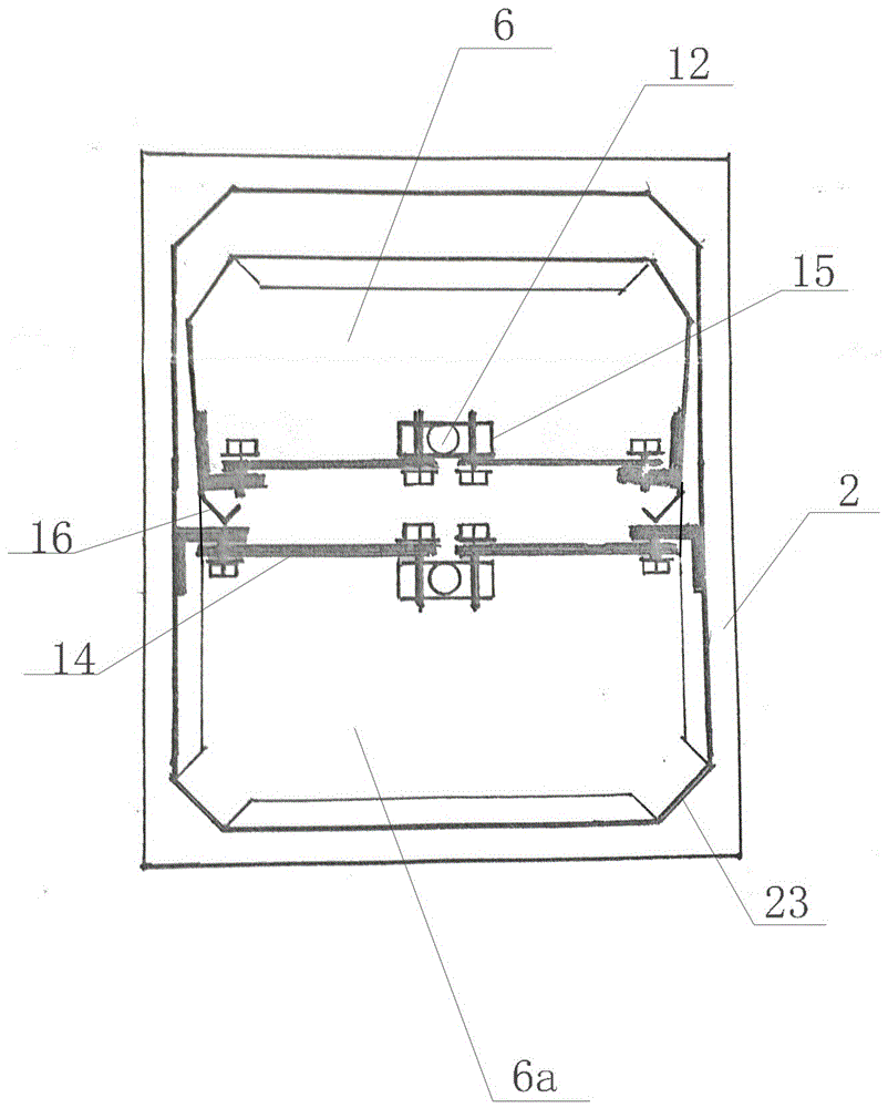
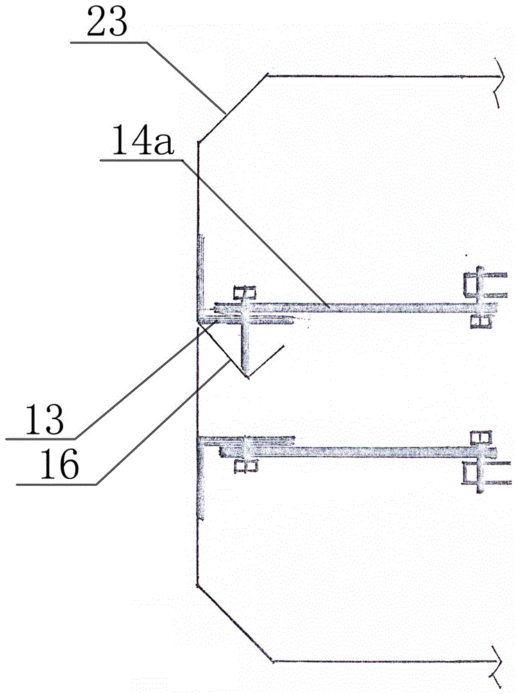
[0026] Such as Figure 1-5 As shown, a mold for prefabricating an exhaust duct of the present invention includes an inner mold and an outer mold, the inner mold includes an inner mold frame 10 and an inner mold frame retractable mechanism 8, and the inner mold frame 10 includes an upper inner mold frame 6a and a support The lower inner mold 6b of the upper inner mold frame 6a, the upper inner mold frame 6a is a C-shaped purlin shape, the lower end of the upper inner mold frame 6a is provided with a buffer 16, the lower inner mold 6b is U-shaped, and the four corners of the inner mold frame 10 23 is an outer chamfer, and the inner wall of the inner mold frame 10 is provided with some transverse reinforcing ribs 11; the outer mold is U-shaped, including the bottom mold frame 19 and the side mold frames 2 hinged on both sides of the bottom mold frame, and the side mold frames on both sides 2. The upper end is fixedly matched by the tie rod 7; the inner mold is placed inside the o...

Embodiment 2

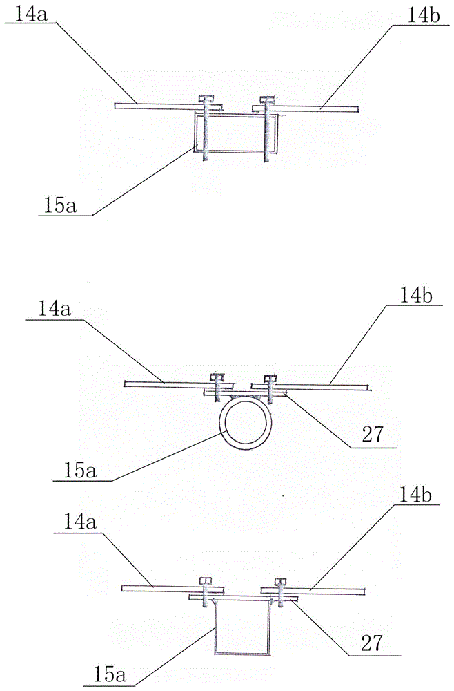
[0038] Such as Figure 6 As shown, the difference between this embodiment and Embodiment 1 lies in that the positions of the handles at both ends of the central rod are different.


PUM

PropertyMeasurementUnit
lengthaaaaaaaaaa
thicknessaaaaaaaaaa
thicknessaaaaaaaaaa

Abstract

The invention discloses a mold of a prefabricated exhaust passage. The mold comprises an inner mold body and an outer mold body. The inner mold body comprises an inner mold frame and inner mold frame extending-retracting mechanisms. The inner mold frame comprises an upper inner mold frame body and a lower inner mold frame body for supporting the upper inner mold frame body. The upper inner mold frame body is in a C-shaped purline shape. Buffer pieces are arranged at the lower end of the upper inner mold frame body. The lower inner mold frame body is in a U shape. The four corners of the inner mold frame are outer chamfers or R corners, and transverse reinforcing ribs are arranged on the inner wall of the inner mold frame. The outer mold body is in a U shape and comprises a bottom mold frame and side mold frames hinged to the two sides of the bottom mold frame, and the upper ends of the side mold frames on the two sides are fixed and matched through a pull rod. The inner mold body is arranged in the outer mold body, a mold cavity is formed between the inner mold body and the outer mold body, end frames are arranged at the two ends of the mold cavity, and the inner mold body is arranged on the end fames. According to the mold of the prefabricated exhaust passage, mechanical mold operation is achieved, losses of the inner mold frame are not prone to happening, and more labor and time are saved during extending and retracting of the inner mold frame.

Description

technical field [0001] The invention relates to the technical field of prefabricated molds for building facilities, in particular to a mold for prefabricating exhaust ducts. Background technique [0002] Usually, the molds for residential exhaust ducts basically only have outer molds, but lack inner molds. The inner molds are made by manual operation. Due to the manual operation site occupying a lot of space, the waste of raw materials is serious, and the wall thickness of the exhaust duct is uneven. Due to the different technical proficiency of workers and specific operations, it is difficult to achieve standardized production of the exhaust duct, and the problem of uneven thickness of the exhaust duct is prone to occur, and the impact force of the collision cannot meet the design requirements. Manufacturers have brought great difficulties and production pressure. [0003] In order to solve the above problems, Chinese patent CN101462300B disclosed a prefabricated thin-wall...

Claims


Application Information

Patent Timeline
Patent Type & Authority Applications(China)
IPC IPC(8): B28B7/16B28B7/00B28B7/28
CPCB28B7/0002B28B7/168B28B7/28
Inventor 魏张木
Owner 魏张木
Why Eureka
Try Eureka