
Passenger side air bag restraint system reinforcing frame

A side airbag and reinforcement frame technology, which is applied in the passenger side airbag reinforcement frame field, can solve the problems of high cost, large mold modification, passenger injury, etc., and achieve the effects of flexible strength adjustment, improved transmission capacity, and guaranteed stability

Active Publication Date: 2017-01-11
SHANGHAIK YANFENG JINQIAO AUTOMOTIVE TRIM SYSTEMS CO LTD
View PDF5 Cites 0 Cited by
  • Summary
  • Abstract
  • Description
  • Claims
  • Application Information

AI Technical Summary

Problems solved by technology

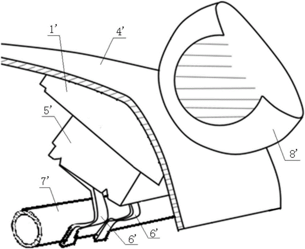
[0003] In order to ensure the stability of the airbag blasting process, the existing airbag reinforcement frame usually has relatively high strength, so that the instrument panel area where the airbag reinforcement frame is installed is also strong, which cannot meet the energy absorption requirements for collision collapse in the national standard GB11552
When a passenger hits the instrument panel assembly 4' accidentally or due to external factors, the collapse amount of the surface of the instrument panel assembly 4' will be small, and the surface of the instrument panel assembly 4' will resist and absorb most of the collision energy. The energy is not effectively transmitted to the airbag bracket 6' and the metal beam 7', and the impact energy cannot be effectively absorbed. The instrument panel cannot relieve the impact energy of the passengers on the instrument panel, and when the impact speed is high, it will cause greater damage to the passengers. harm
[0004] At present, in order to solve the above problems, the structural design of the instrument panel is usually changed, but these changes often bring about the problems of large amount of mold modification, high cost, and long cycle time, and every time the structure is changed, airbag blasting and collision tests are required. Verification, which greatly increases the development cost

Method used


Image

  • Passenger side air bag restraint system reinforcing frame
  • Passenger side air bag restraint system reinforcing frame
  • Passenger side air bag restraint system reinforcing frame

Examples


Embodiment Construction

[0027] According to the attached Figure 2-9 , give a preferred embodiment of the present invention, and give a detailed description, so that the functions and characteristics of the present invention can be better understood.

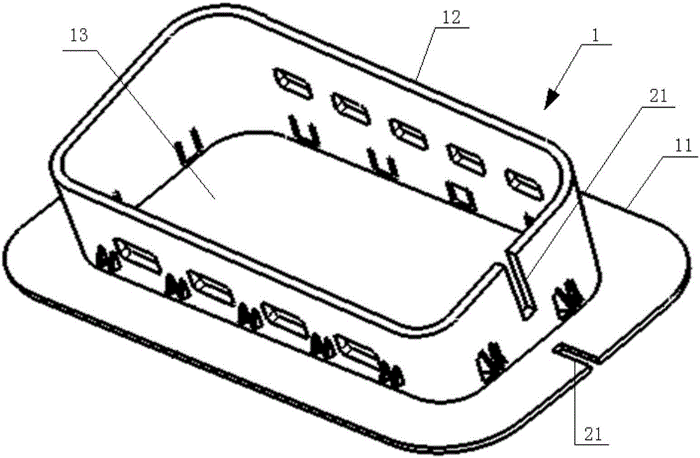
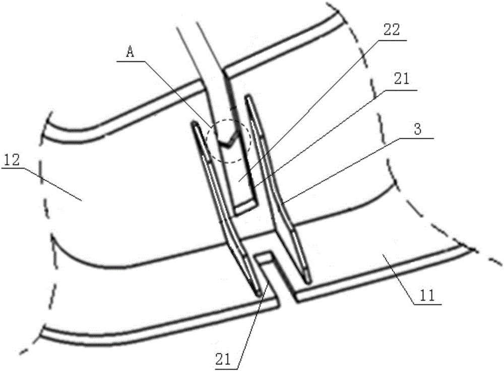
[0028] see figure 2 , a passenger side airbag reinforcement frame 1 according to Embodiment 1 of the present invention includes an airbag reinforcement frame body, two strength weakening structures are arranged on the airbag reinforcement frame body, and the number of strength weakening structures can be determined according to other embodiments. Adjustment is required. As long as the structural space of the airbag reinforcement frame 1 on the passenger side allows, the strength weakening structure can be applied to any position of the side wall edge and the substrate edge of the airbag reinforcement frame 1 .

[0029] Such as figure 2 As shown, wherein the airbag reinforcement frame body includes a base plate 11 and a side frame body 12 extending...


PUM


Abstract

The invention provides a passenger side air bag restraint system reinforcing frame which comprises an air bag reinforcing frame body. The air bag reinforcing frame body comprises a base plate and a side frame body. An air bag door is formed on the base plate. The bottom face of the side frame body is fixed to the periphery of the air bag door. The area of the base plate is larger than the area formed by surrounding the bottom face of the side frame body. At least one strength weakening structure is formed on the side frame body or the side frame body and the base plate form at least one strength weakening structure. The strength weakening structure comprises an open slot. The passenger side air bag restraint system reinforcing frame is provided with the strength weakening structure, on the basis of ensuring the safety and stability of the air bag explosion process, the requirement for energy absorption of collision collapse in the national standard GB11552 is met, and the passenger side air bag restraint system reinforcing frame has the advantages of being simple in structure, low in cost and high in safety.

Description

technical field [0001] The invention relates to the field of automobile safety airbags, in particular to a passenger side safety airbag reinforcement frame. Background technique [0002] At present, in order to reduce the injuries caused by collision accidents during driving, most vehicles will be equipped with airbags. The airbag on the passenger's side is arranged inside the instrument panel, and is connected to the instrument panel through the airbag reinforcement frame, which is used to fix the airbag and guide the expansion direction of the airbag after it explodes. see figure 1 The passenger side airbag structure of the existing automobile generally includes: an airbag reinforcement frame 1', an instrument panel body 4', an airbag module 5', two airbag brackets 6' and a metal beam 7', and the airbag reinforcement frame 1' uses vibration friction It is connected to the instrument panel body 4' by welding, and the airbag module 5' is fixedly installed in the side frame...

Claims


Application Information

Patent Timeline
Patent Type & Authority Applications(China)
IPC IPC(8): B60R21/205
CPCB60R21/205B60R2021/161
Inventor 郑占明董安奎巫建清
Owner SHANGHAIK YANFENG JINQIAO AUTOMOTIVE TRIM SYSTEMS CO LTD
Learn More