Rotor spinning false twister

A false twist disc and rotor spinning technology, applied in the field of rotor spinning false twist discs, can solve the problems of increasing yarn friction, accumulating dust or impurities, reducing the service life of false twist discs and false twist efficiency, and achieving The effect of reducing head breaks

Inactive Publication Date: 2017-01-11
JIANGSU PUMEI TEXTILE CO LTD
View PDF7 Cites 0 Cited by
  • Summary
  • Abstract
  • Description
  • Claims
  • Application Information

AI Technical Summary

Problems solved by technology

In the prior art, in order to improve the false-twisting efficiency of the false-twisting disk, the arc surface of the false-twisting disk is usually processed on the false-twisting disk, and generally grooves are engraved on the curved surface of the false-twisting disk (the false twisting disk does not penetrate through the hole). The upper and lower bottom surfaces) or protrusions increase the roughness of the arc surface of the false twist disc, thereby increasing the friction of the yarn on the s

Method used


Image

  • Rotor spinning false twister
  • Rotor spinning false twister
  • Rotor spinning false twister

Examples


Example Embodiment

[0026] Example 1

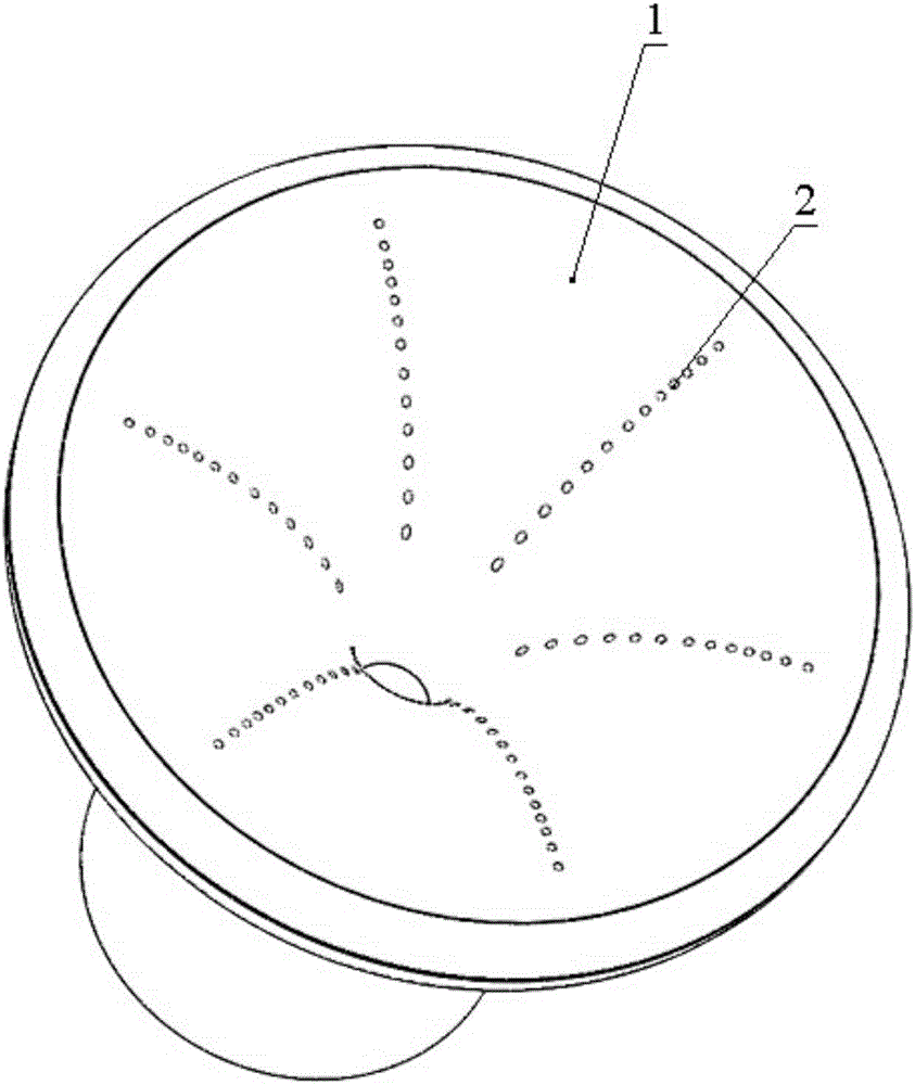
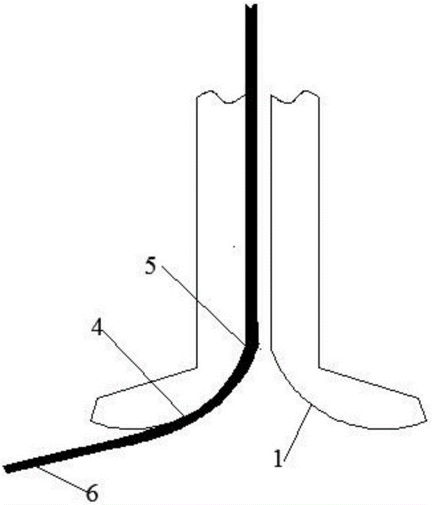
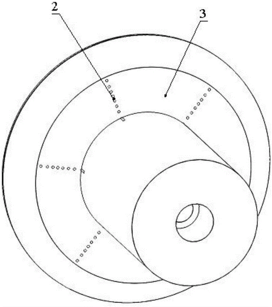
[0027] A false twist disk for rotor spinning, the structure is as follows Figure 1-3 As shown, the arc surface part 1 of the false twist disc body has a through hole 2, image 3 The position of the lower bottom surface 3 of the arc surface part of the false twist disc body is shown in , the through hole 2 runs through the upper bottom surface of the arc surface part of the false twist disc body and the lower bottom surface of the arc surface part of the false twist disc body, and the through holes are distributed in the yarn 6 from the rotor cup From the initial contact point 4 of the inner lead and the arc surface 1 of the false twisting disc to the arc surface part of the connection point 5 between the yarn drawing tube and the arc surface 1 of the false twisting disc, a through hole is opened along the direction of the generatrix of the arc part 1 of the false twisting disc body to form a strip There are 1 group of strip-shaped through-hole groups in th...

Example Embodiment

[0028] Example 2

[0029] Disclosed is a false twist disk for rotor spinning, wherein a through hole 2 is opened on the arc surface part 1 of the body of the false twist disk. The through holes are distributed in the arc surface part where the yarn 6 is drawn from the rotor cup from the initial contact point 4 with the arc surface 1 of the false twist disc to the connection point 5 between the yarn drawing tube and the arc surface 1 of the false twist disc, along the arc surface of the false twist disc body There are through holes in the direction of part of the busbar to form a strip-shaped through-hole group. The number of strip-shaped through-hole groups in the arc surface of the false twist disc body is 8 groups. There are 10 through-holes in the strip-shaped through-hole group, and the shape of the through-holes is 2. It is elliptical, and the cross-sectional area of ​​the through hole 2 is 0.1mm 2 , the material of the arc surface part of the false twist disc body is st...

Example Embodiment

[0030] Example 3

[0031] Disclosed is a false twist disk for rotor spinning, wherein a through hole 2 is opened on the arc surface part 1 of the body of the false twist disk. The through holes are distributed in the arc surface part where the yarn 6 is drawn from the rotor cup from the initial contact point 4 with the arc surface 1 of the false twist disc to the connection point 5 between the yarn drawing tube and the arc surface 1 of the false twist disc, along the arc surface of the false twist disc body Through holes are opened in the direction of some busbars to form strip-shaped through-hole groups. The number of strip-shaped through-hole groups set in the arc surface of the false twist disc body is 4 groups. There are 20 through-holes in the strip-shaped through-hole group, and the shape of the through-holes is 2. It is a rhombus, and the cross-sectional area of ​​the through hole 2 is 0.1mm 2 , the material of the arc surface part of the false twist disk body is ceram...


PUM

PropertyMeasurementUnit
Cross-sectional areaaaaaaaaaaa
Breaking strengthaaaaaaaaaa

Abstract

The invention discloses a rotor spinning false twister. Through holes penetrating a cambered surface are formed in the cambered surface of a false twister body and connected with external fans, and air exhaust functions are achieved. When yarns are spun in a rotor spinning manner, the yarns can be adsorbed at the through holes by external negative pressure, friction action among the spun yarns and the cambered surface of the false twister body can be increased, so that false twisting action of the false twister is enhanced, and end breakage is decreased when the yarns are spun in the rotor spinning manner. The rotor spinning false twister can effectively solve the problem of end breakage in rotor spinning of combed noil yarns below 14.7tex, and can help enterprises to effectively upgrade industries and save production cost.

Description

technical field [0001] The invention belongs to the field of spinning equipment, and relates to a false twist disk for rotor spinning, in particular to a false twist disk for rotor spinning with through holes on the arc surface of the false twist disk. Background technique [0002] Rotor spinning is also called air-end spinning in our country. It is a new type of spinning technology and belongs to the category of open-end spinning technology. Due to the advantages of high production efficiency, good yarn evenness, short process flow, good working environment and high degree of automation, rotor spinning is currently the most popular new spinning form. Rotor spinning has become more popular in my country, and its total production of cotton yarn is second only to ring spinning. Therefore, rotor spinning also has a greater influence in the spinning industry and plays a pivotal role. [0003] During cotton spinning, the sliver produced by the carding machine will have many def...

Claims


Application Information

Patent Timeline
IPC IPC(8): D01H4/10
CPCD01H4/10
Inventor 尤良春杨军沈加民
Owner JIANGSU PUMEI TEXTILE CO LTD
Why Eureka
Try Eureka