Bridge deck drainage supporting facility

A facility and drainage channel technology, used in bridge construction, bridges, bridge parts, etc., can solve the problems of exposed drainage pipes, leakage of water at the interface, etc., and achieve the effects of convenient maintenance, good sealing, and convenient operation and replacement.

Active Publication Date: 2017-01-11
BEIJING GENERAL MUNICIPAL ENG DESIGN & RES INST
View PDF10 Cites 1 Cited by
  • Summary
  • Abstract
  • Description
  • Claims
  • Application Information

AI Technical Summary

Problems solved by technology

[0003] The purpose of the present invention is to provide a bridge deck drainage supporting facility to solve the problems of exposed drain pipes and frequent water leakage at the interface in the traditional bridge deck drainage scheme

Method used


Image

  • Bridge deck drainage supporting facility
  • Bridge deck drainage supporting facility
  • Bridge deck drainage supporting facility

Examples


Embodiment Construction

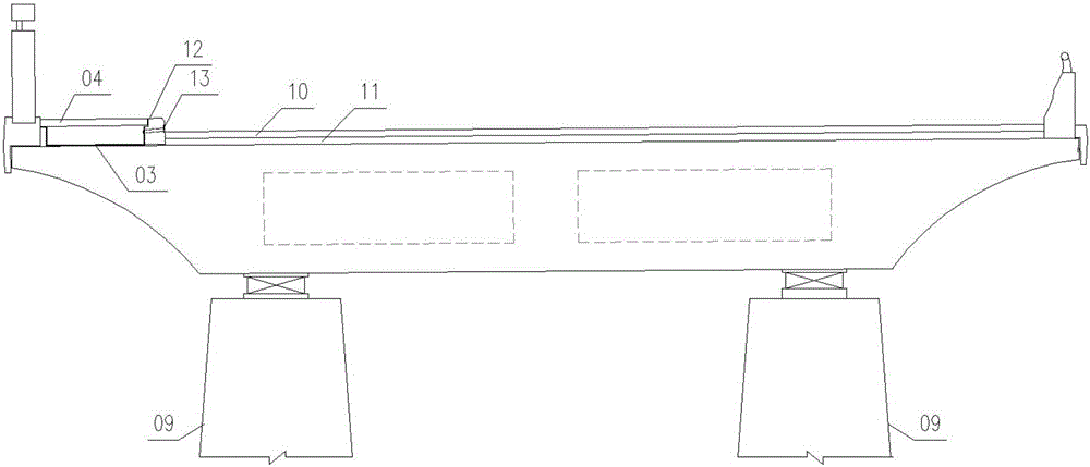
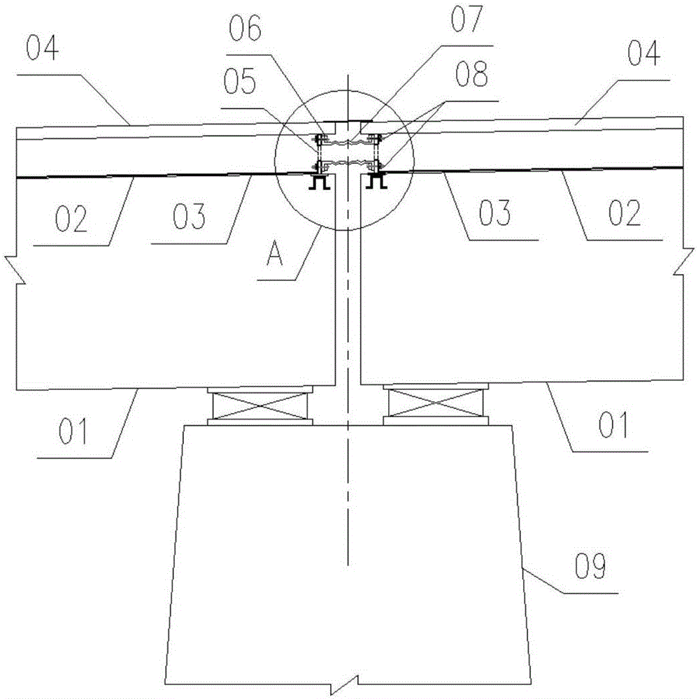
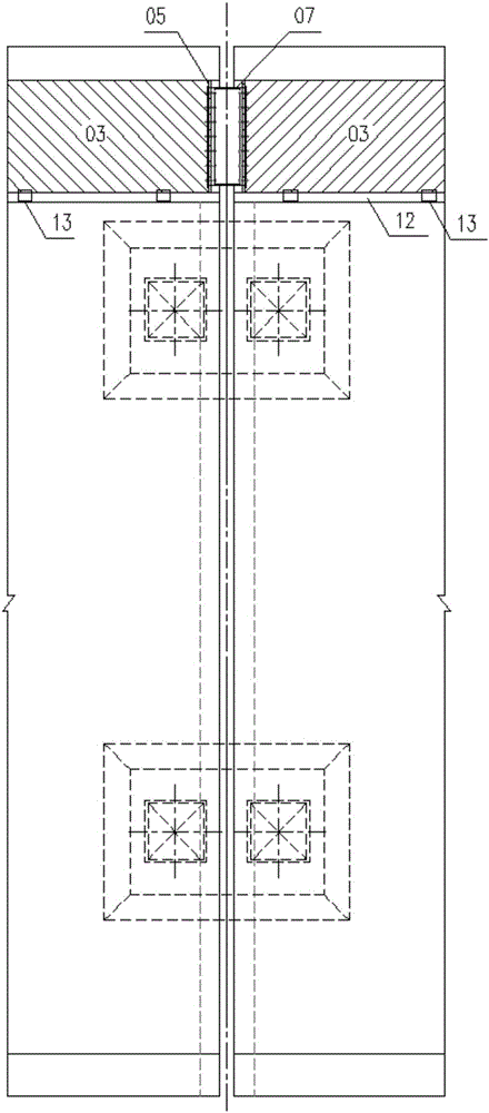
[0018] Concrete structure of the present invention, see figure 1 , 2 , 3, 4 shown.

[0019] First, determine the cross-sectional area of ​​the drainage groove according to the length, width and longitudinal slope of the bridge, and use the height of the walkway above the roadway (or non-motorized vehicle lane) and the pavement thickness of the roadway (or non-motorized vehicle roadway), The cross-section of the set drainage groove is realized by cutting grooves on the top surface of the bridge beam body under the footpath.

[0020] Specifically, drainage grooves are set outside the curb stones on the bridge deck. To facilitate construction, the drainage grooves adopt an open rectangular section, and the top of the drainage grooves is covered with a walkway cover.

[0021] In order to ensure the service life of the gutter and avoid corrosion to the concrete beam, the gutter is wrapped with a stainless steel plate. There are horizontal rainwater holes on the edge stone. The ...


PUM


Abstract

The invention discloses a bridge deck drainage supporting facility. A drainage channel is formed in the outer side of a bridge deck pavement edge curb and provided with an open rectangular section, a footpath cover plate covers the upper portion of the drainage channel, the outside of the drainage channel is wrapped with a stainless steel plate, rainwater holes are formed in the curb, the drainage channel extends into linking roads at two ends of a bridge along the bridge, a spherical rubber expansion joint for water passage is formed in the position of the drainage channel passing an expansion seam, two ends of the rubber expansion joint are fastened on vertical seal head steel plates of the drainage channel through flange plates and bolts, openings are formed in the vertical seal head steel plates of the drainage channel and correspond to the expansion joint, the stainless steel plate externally wrapping the drainage channel is crimped at the openings of the seal head steel plates, the stainless steel plate, the rubber expansion joint and the flange plates are jointly anchored on a steel plate, a plurality of spheres are formed on the vertical surface of the rubber expansion joint, the displacement deformation requirement of beams on two sides of the expansion seam is met, and the cross section of the expansion joint is rectangular. The bridge deck drainage supporting facility can solve the problems that a drainage pipe of a traditional bridge deck drainage scheme is exposed, joints frequently leak and the like.

Description

technical field [0001] The invention relates to a bridge deck drainage supporting facility. Background technique [0002] The conventional bridge deck drainage scheme generally adopts the method of collecting rainwater through the bridge deck gully, then entering the vertical drainage pipe through the vertical drainage pipe, and then uniformly discharging it into the downpipe at the pier column into the ground rainwater system. The vertical drainage pipe is generally suspended at the bottom of the cantilever of the main beam, which affects the appearance of the bridge. At the same time, water leakage often occurs at the interface with the vertical drainage pipe, which affects the use effect. Contents of the invention [0003] The purpose of the present invention is to provide a bridge deck drainage supporting facility to solve the problems of exposed drain pipes and frequent water leakage at the interface in the traditional bridge deck drainage scheme. [0004] In order t...

Claims


Application Information

Patent Timeline
Patent Type & Authority Applications(China)
IPC IPC(8): E01D19/08
CPCE01D19/086
Inventor 秦大航张为杨冰韦立许志宏李建民惠斌梁志超岳嘉杨文忠赵维贺李健刚罗飞宁晓旭
Owner BEIJING GENERAL MUNICIPAL ENG DESIGN & RES INST
Why Eureka
Try Eureka