Sponge engineering system based on existing urban road and drainage condition and construction method of sponge engineering system

A technology for roads and cities, which is applied in the sponge engineering system and its construction field, can solve the problems of large current road disturbance, daily traffic order interference, and damage to existing road surfaces, etc., to reduce municipal drainage pressure, facilitate construction, and eliminate surface runoff Effect

Active Publication Date: 2017-01-11
南京紫城工程设计有限公司
View PDF5 Cites 4 Cited by
  • Summary
  • Abstract
  • Description
  • Claims
  • Application Information

AI Technical Summary

Problems solved by technology

[0004] In the existing technology, for the existing urban roads with complete pavement and large traffic flow, the urban road sections that are not suitable for road surface reconstruction, the reconstruction method to solve the road surface water will greatly disturb the current road, such as the reconstruction method of thickening the traditional drainage pipe Not only will it damage the existing road surface, resulting in a large amount of engineering, but also need to close the road surface for construction, which will interfere with the daily traffic order

Method used


Image

  • Sponge engineering system based on existing urban road and drainage condition and construction method of sponge engineering system
  • Sponge engineering system based on existing urban road and drainage condition and construction method of sponge engineering system
  • Sponge engineering system based on existing urban road and drainage condition and construction method of sponge engineering system

Examples


Embodiment Construction

[0043]The present invention will be further described below in conjunction with the accompanying drawings and specific embodiments.

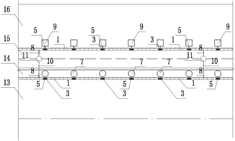
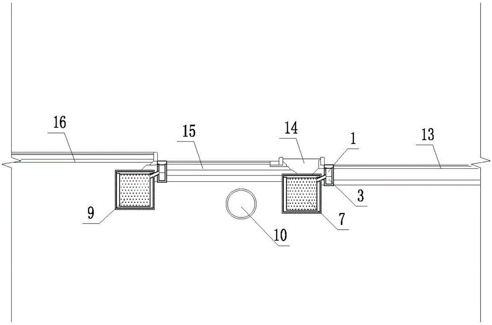
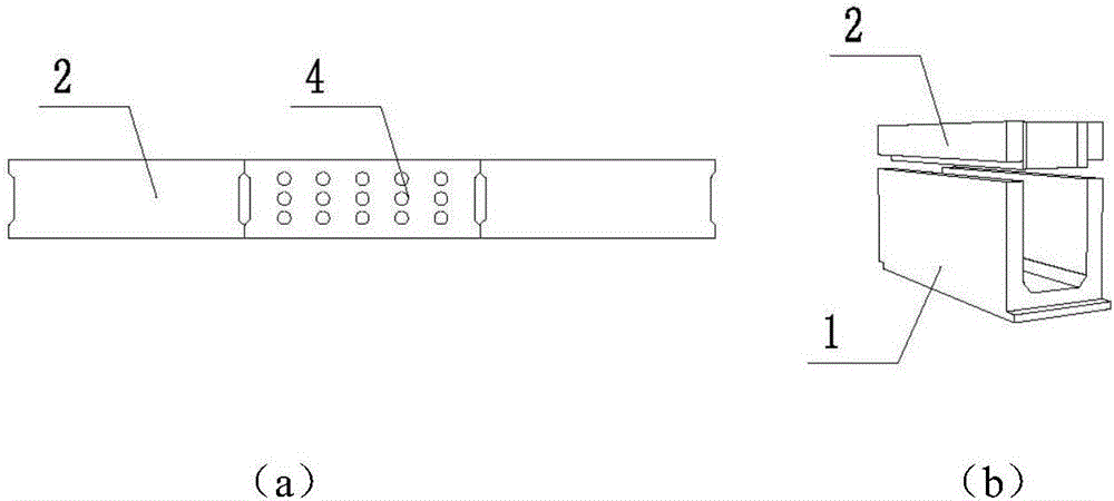
[0044] Figure 1-8 The reference signs are: water collection side ditch 1, gap cover plate 2, dredging well 3, dredging well cover plate 4, collecting pipe 5, waste intercepting basket 6, circular seepage storage tank 7, overflow pipe 8, square Seepage storage tank 9, municipal rainwater pipe 10, municipal rainwater well 11, gravel layer 12 with a particle size of 15-25 mm, motor vehicle lane 13, side belt 14, non-motor vehicle lane 15, sidewalk 16 and tree planting digging machine 17, among which municipal The rainwater pipe 10 and the municipal rainwater well 11 are existing drainage facilities, and the municipal rainwater pipe 10 is connected to the bottom of the municipal rainwater well 11 .

[0045] Sponge engineering system based on existing urban roads and drainage conditions, including water collection side ditch 1, gap cover plate 2, d...


PUM


Abstract

The invention discloses a sponge engineering system based on an existing urban road and a drainage condition and belongs to the technical field of urban road drainage and rainwater utilization. Road surfaces of a motorized vehicle lane, a non-motorized vehicle lane and a pavement keep unchanged; water collection side ditches are formed in an outer side of the motorized vehicle lane along a road flat teeth part, and a road flat teeth part between the non-motorized vehicle lane and the pavement; gap cover plates cover the water collection side ditches; dredging wells are arranged along the water collection side ditches every 5m to 6m; the water collection side ditches are connected with a round water seepage and storage tank and a square water seepage and storage tank through inclined collection pipes respectively; the water collection side ditches are connected with a municipal rainwater pipe through overflow pipes. The invention further discloses a construction method of the system. By adopting the sponge engineering system and the construction method, an existing drainage system is not changed and burden of downstream drainage is effectively alleviated; pollution to a downstream water body, caused by initial rainwater pollution of the road surface, is avoided; disturbance on the existing rod surface and arbor planting is not caused; the construction is convenient and the road does not need to be blocked; interference to traffic is not caused, water resources are saved and the sponge engineering system and the construction method have promotional value.

Description

technical field [0001] The invention belongs to the technical field of urban road drainage and rainwater utilization, and in particular relates to a sponge engineering system based on existing urban road and drainage conditions and a construction method thereof. [0002] technical background [0003] In recent years, road waterlogging caused by heavy rainfall has been a chronic disease that affects pedestrian travel and even endangers urban traffic safety. It is common in Chinese cities. On the one hand, traditional asphalt or cement pavement surface drainage can only be carried out through storm water outlets, which is time-consuming It is long and prone to air resistance, and poor drainage leads to water on the road, which will not only cause vehicle tires to slip and become a safety hazard, but in areas with more water, it will seriously cause vehicles to be soaked in water and be scrapped, and pollutants will overflow to cause environmental pollution; On the one hand, the...

Claims


Application Information

Patent Timeline
Patent Type & Authority Applications(China)
IPC IPC(8): E03F1/00E03F5/10E03F11/00E01C11/22
CPCE01C11/227E03F1/005E03F5/10E03F11/00Y02A30/60
Inventor 成玉宁成实
Owner 南京紫城工程设计有限公司
Why Eureka
Try Eureka