Transmission shaft seal structure

A technology of sealing structure and transmission shaft, which is applied in the direction of transmission components, transmission parts, components with teeth, etc., can solve the problems of equipment appearance and environmental sanitation maintenance, leakage of sealing ring lubricating oil, waste of lubricating oil, etc. Achieve the effect of simple structure, avoid waste and prevent seepage

Inactive Publication Date: 2017-01-11
NANJING KISEN INT ENG
View PDF7 Cites 3 Cited by
  • Summary
  • Abstract
  • Description
  • Claims
  • Application Information

AI Technical Summary

Problems solved by technology

However, this is not the case in actual applications. Lubricating oil often seeps out from the sealing ring at the transmission shaft, which not only

Method used


Image

  • Transmission shaft seal structure
  • Transmission shaft seal structure
  • Transmission shaft seal structure

Examples


Example Embodiment

[0016] In order to make the objectives, technical solutions, and advantages of the present invention clearer, the present invention will be further described in detail below in conjunction with specific embodiments and drawings. Here, the exemplary embodiments of the present invention and the description thereof are used to explain the present invention, but not as a limitation to the present invention.

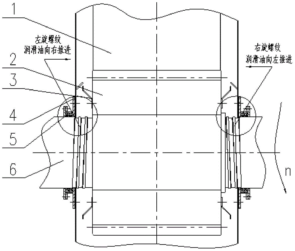
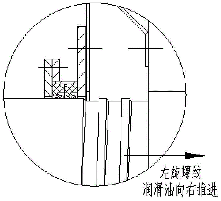
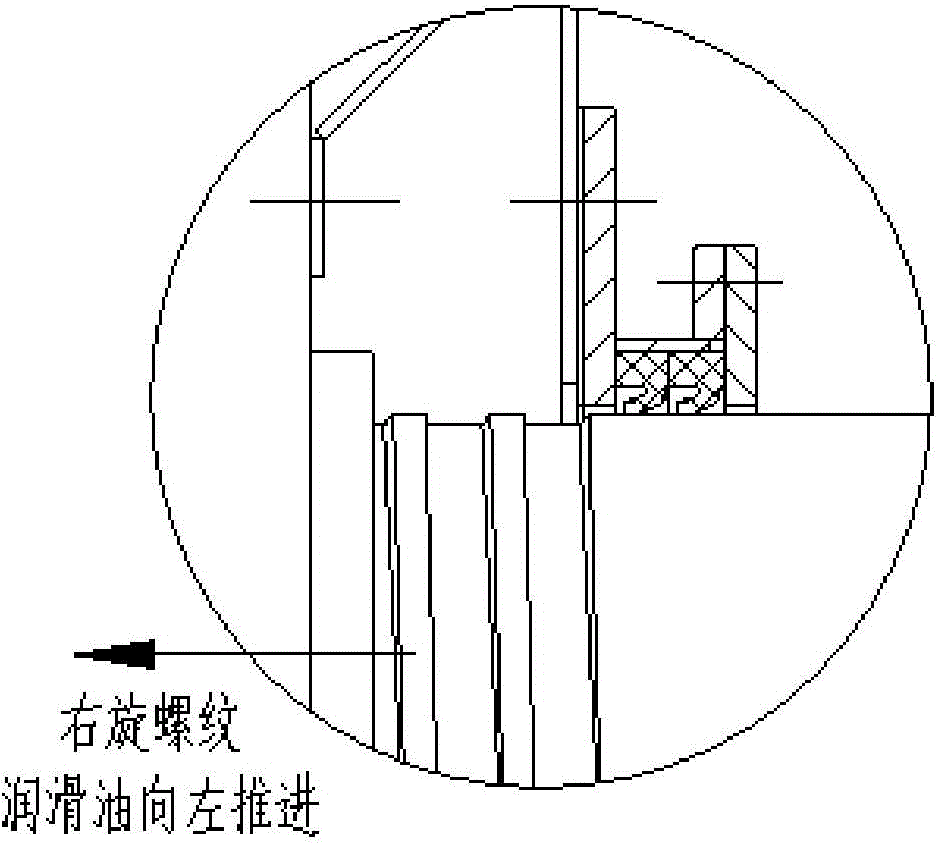
[0017] Such as Figure 1-3 As shown, the transmission shaft sealing structure of the present invention is composed of a large gear 1, a small gear 2, an oil baffle ring 3, a sealing bracket 4, a lip seal ring 5 and a transmission shaft 6; the small gear 2 and the large gear 1 form Meshing connection; small gear 2 drives large gear 1 to rotate; small gear 2 is in the shape of a hollow ring; a transmission shaft 6 with threaded structures on both sides passes through the hollow part of small gear 2, and the two form a fixed connection; Seen from the right to the left, the steerin...


PUM


Abstract

The invention relates to a seal structure, in particular to a transmission shaft seal structure. The structure is composed of a large gear, a small gear, an oil blocking ring, a seal support, a lip-shaped seal ring and a transmission shaft; in the technical scheme, a thread structure is machined on the proper position of the transmission shaft, rotation of the transmission shaft drives lubricating oil deposited in the thread portion on the transmission shaft to move inwards, overflowing lubricating oil returns to a reserved flowing rail again, and due to the combination manner of the lubricating oil and the lip-shaped seal ring, seal between the transmission shaft and the small gear is more reliable; meanwhile, the lubricating oil can be prevented from seeping out, lubricating oil waste is avoided, and the advantages of being simple in structure, clean and sanitary are achieved.

Description

technical field [0001] The invention relates to a sealing structure, in particular to a transmission shaft sealing structure. Background technique [0002] Tube mill is a kind of pulverizer, and it is also a very important fine grinding equipment in modern industry. It is a cylinder with supporting devices at both ends, which contains grinding bodies or grinding media; the cylinder rotates around the horizontal central axis, the grinding media is brought to a certain height by friction and then falls, and the material passes through the cylinder continuously , so that it is continuously impacted, extruded and ground by the grinding medium, and finally ground into a qualified product; the tube mill is widely used in building materials, metallurgy, mineral processing, electric power and chemical industries to grind cement and other materials; it has a large crushing ratio, production It has the characteristics of large capacity, strong adaptability to materials, and easy repl...

Claims


Application Information

Patent Timeline
IPC IPC(8): F16H57/023F16H57/029F16H57/04
CPCF16H57/023F16H57/029F16H57/0472F16H2700/00
Inventor 张志红
Owner NANJING KISEN INT ENG
Why Eureka
Try Eureka