Connecting flange valve for water collecting pipe and concealed draining pipe

A technology for connecting flanges and water collection pipes, which is applied in the field of connecting flange valves between water collection pipes and drain pipes. It can solve problems such as wall abrasion and scratches, unfavorable valve operation and control, and failure to automatically compensate, so as to increase airtightness, Improved airtightness and reduced friction

Inactive Publication Date: 2017-01-11
SHANDONG SUNWAY LANDSCAPE TECH
View PDF10 Cites 11 Cited by
  • Summary
  • Abstract
  • Description
  • Claims
  • Application Information

AI Technical Summary

Problems solved by technology

[0003] The purpose of the present invention is to provide a flanged valve connecting the water collecting pipe and the drain pipe to solve the problem that the common connecting valve design mentioned in the above background technology has large fluid resistance, slow switching, slow flow adjustment speed, and poor sealing performance after the valve is closed. To ensure that the rotation resistance of the valve plate is large, the switch operation is not flexible, which is not conducive to the operation and control of the valve, and it is easy to cause leakage due to wall abrasion and scratches. Due to structural reasons, the valve body and valve seat cannot be automatically compensated after wear. , the problem of frequent maintenance and replacement

Method used


Image

  • Connecting flange valve for water collecting pipe and concealed draining pipe
  • Connecting flange valve for water collecting pipe and concealed draining pipe
  • Connecting flange valve for water collecting pipe and concealed draining pipe

Examples


Embodiment Construction

[0015] The following will clearly and completely describe the technical solutions in the embodiments of the present invention with reference to the accompanying drawings in the embodiments of the present invention. Obviously, the described embodiments are only some, not all, embodiments of the present invention. Based on the embodiments of the present invention, all other embodiments obtained by persons of ordinary skill in the art without making creative efforts belong to the protection scope of the present invention.

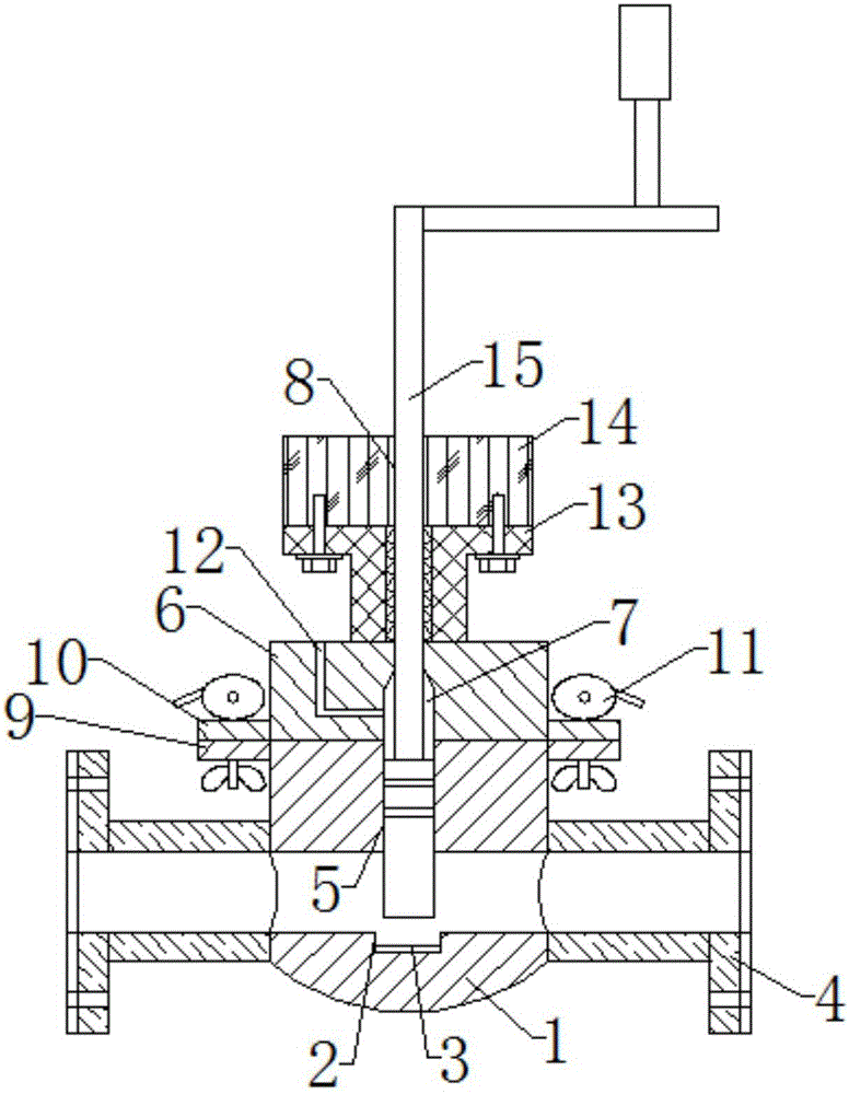
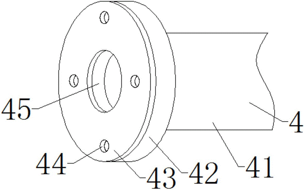
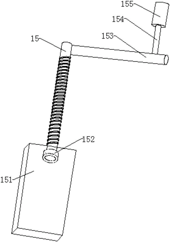
[0016] see Figure 1-5 , the present invention provides a technical solution: the flange valve connecting the water collecting pipe and the drain pipe includes a valve seat 1, the bottom of the inner cavity of the valve seat 1 is provided with a groove 2, and the inner wall of the groove 2 is provided with a rubber Pad 3, the left wall and the right wall of the valve seat 1 are provided with a flange 4, the top middle of the valve seat 1 is provided with a chu...


PUM


Abstract

The invention discloses a connecting flange valve for a water collecting pipe and a concealed draining pipe in the technical field of valves. The connecting flange valve comprises a valve seat. A groove is formed in the bottom of an inner cavity of the valve seat. A rubber gasket is arranged on the inner wall of the groove. Flange plates are arranged on the left wall and the right wall of the valve seat correspondingly. A sliding groove is formed in the middle of the top of the valve seat and communicates with the inner cavity of the valve seat. According to the connecting flange valve for the water collecting pipe and the concealed draining pipe, the groove is formed in the bottom of the inner cavity of the valve seat, and the rubber gasket is arranged on the inner wall of the groove, so that the leakproofness during baffle closing is improved, and a water blocking effect is effectively achieved; due to the fact that a sliding cavity with the size the same as that of the sliding groove is formed in the bottom of a valve deck, due to the sliding cavity, a baffle can conveniently enter the sliding cavity when opened, and the inner cavity of the valve seat can be completely opened; and an oil hole is formed in the top of the valve deck, the right end of the oil hole communicates with the sliding cavity, lubricating oil can be injected from the oil hole when friction between the baffle and the sliding groove is relatively large, and therefore friction is reduced.

Description

technical field [0001] The invention relates to the technical field of valves, in particular to a flange valve connecting a water collecting pipe and a draining hidden pipe. Background technique [0002] At present, in the field of pipeline fluid control in water conservancy, fire protection, petroleum, chemical industry and other industries, the valve body and pipeline device are realized by welding. After long-term use, it is not easy to disassemble, repair and replace. Ordinary connecting valves are designed with large fluid resistance and slow switching. The speed of flow adjustment is slow, the sealing performance after the valve is closed cannot be guaranteed, the rotation resistance of the valve plate is large, and the switch operation is not flexible, which is not conducive to the operation and control of the valve, and it is easy to cause leakage due to wall abrasion and scratches. Due to structural reasons, the seat cannot be automatically compensated after wear an...

Claims


Application Information

Patent Timeline
Patent Type & Authority Applications(China)
IPC IPC(8): F16K3/02F16K3/314F16K3/36F16K31/50F16K31/60
CPCF16K3/0236F16K3/0281F16K3/314F16K3/36F16K31/504F16K31/602
Inventor 王胜
Owner SHANDONG SUNWAY LANDSCAPE TECH
Why Eureka
Try Eureka