Large-flow type pneumatic shut-off directional valve

A large flow, reversing valve technology, applied to valve details, multi-way valves, valve devices, etc., can solve problems such as damage, increased maintenance costs, material waste, etc., and achieve the effect of ensuring good response time and stability of work

Active Publication Date: 2017-01-11
WENZHOU REBECCA HYGIENIC PROCESSING SYST
View PDF4 Cites 0 Cited by
  • Summary
  • Abstract
  • Description
  • Claims
  • Application Information

AI Technical Summary

Problems solved by technology

However, as a vulnerable part, the spring is often damaged during long-term and high-load use, and its service life is much shorter than the service life of the valve, which will not only cause waste of materials, but also increase maintenance costs.

Method used


Image

  • Large-flow type pneumatic shut-off directional valve
  • Large-flow type pneumatic shut-off directional valve
  • Large-flow type pneumatic shut-off directional valve

Examples


Embodiment Construction

[0033] The following specific descriptions of the present invention are given by the examples, which are only used to further illustrate the present invention, and should not be construed as limiting the protection scope of the present invention.

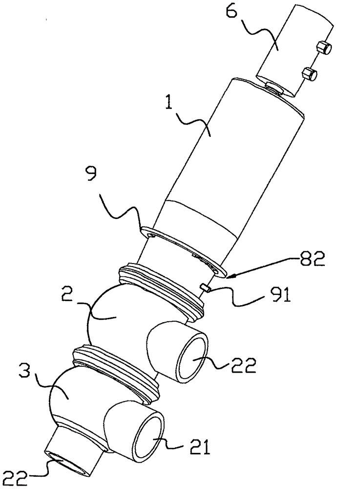
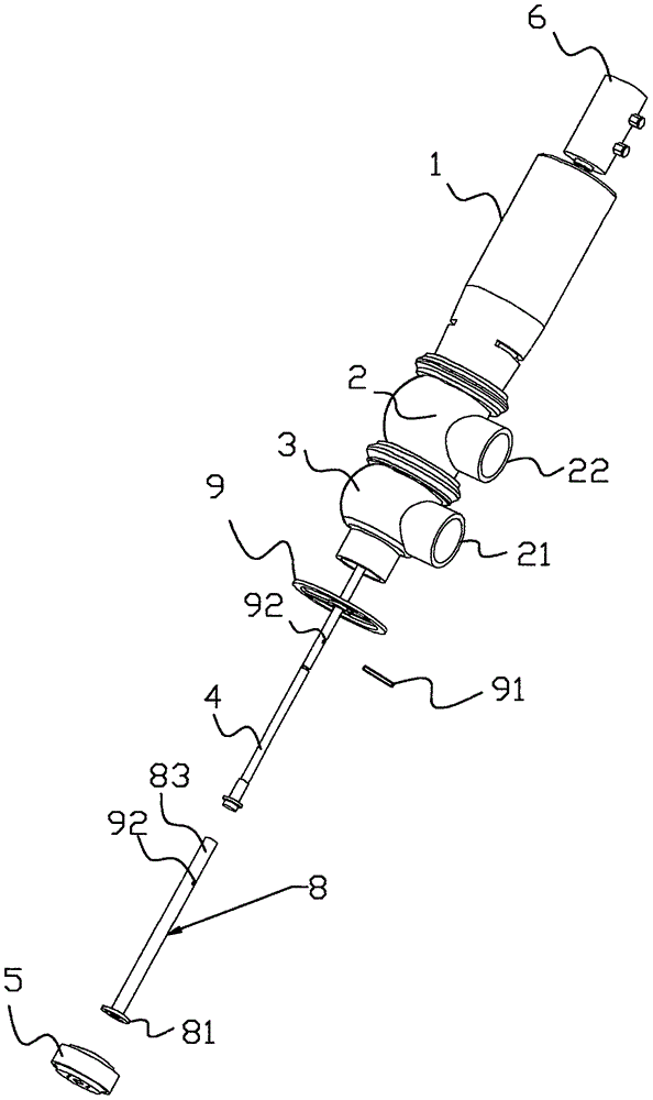
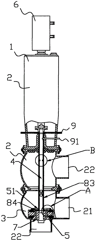
[0034] 1. If Figure 1-7The specific embodiment of the present invention shown is a large flow type pneumatic cut-off reversing valve, including a valve seat 1, an upper valve body 2 and a lower valve body 3, and the upper valve body 2 and the lower valve body 3 are respectively There is a feed port 21 and a discharge port 22 for the liquid medium to flow in or out. The valve seat 1, the upper valve body 2 and the lower valve body 3 are sequentially connected and communicated with each other. Over the upper valve body 2 and extending to the valve stem 4 in the lower valve body 3, the end of the valve stem 4 located in the lower valve body 3 is provided with a lower valve disc 5 closing the discharge port 22, the lower valve disc 5 ...


PUM


Abstract

A large-flow type pneumatic shut-off directional valve comprises a valve seat, an upper valve body and a lower valve body. A feed inlet for allowing a liquid media to flow in is formed in one side of the upper valve body, and a discharge outlet for allowing the liquid media to flow out is formed in one side of the lower valve body. The valve seat, the upper valve body and the lower valve body are connected in sequence and communicate with one another. A valve rod penetrating through the upper valve body and extending into the lower valve body is arranged in the valve seat. The end, located in the lower valve body, of the valve rod is provided with a lower-end valve clack for sealing the discharge outlet. The end, facing the valve seat, of the lower-end valve clack is the obverse side, and the section, away from the valve seat, of the lower-end valve clack is the reverse side. The other end of the valve rod extends out of the valve seat and is provided with a pneumatic assembly for driving the valve rod to move. The lower-end valve clack is provided with a first filtering hole enabling the obverse side and the reverse side to communicate, and further provided with a filtering hole sealing device for controlling the first filtering hole to be through. The filtering hole sealing device comprises a rotary lower-end valve clack corresponding to the first filtering hole in position, and a locking mechanism for controlling the rotary lower-end valve clack to rotate.

Description

technical field [0001] The invention relates to the technical field of valves, in particular to a pneumatic cut-off reversing valve. Background technique [0002] Traditional pneumatic cut-off reversing valves such as patent number: 201320654988.4 Invention name Manual pneumatic cut-off reversing valve The existing cut-off valves mentioned include valve seats and valve bodies at all levels. The valve body is provided with a material inlet and a material outlet. The valve stem in the valve seat passes through each valve body, and the valve stem is provided with a valve disc that matches the inlet and outlet ends of the valve body, relying on the movement of the valve stem to drive the lower valve disc to block or open the port of the valve body, so as to move the The material port is connected with different material outlets to achieve the purpose of reversing. When the valve is opened or closed, the existing pneumatic cut-off reversing valve drives the lower disc by driving ...

Claims


Application Information

Patent Timeline
Patent Type & Authority Applications(China)
IPC IPC(8): F16K11/044F16K31/60F16K31/12B01D35/04
CPCB01D35/04F16K11/044F16K31/12F16K31/60
Inventor 蔡学炎
Owner WENZHOU REBECCA HYGIENIC PROCESSING SYST
Why Eureka
Try Eureka