Evaporative type condenser
An evaporative condenser and heat exchange plate technology, applied in steam/steam condensers, lighting and heating equipment, etc., can solve the problems of large steam flow resistance and uneven distribution of cooling water, achieve uniform water distribution and reduce drift Water, the effect of improving heat exchange efficiency
- Summary
- Abstract
- Description
- Claims
- Application Information
AI Technical Summary
Problems solved by technology
Method used
Image

Examples
Embodiment 1
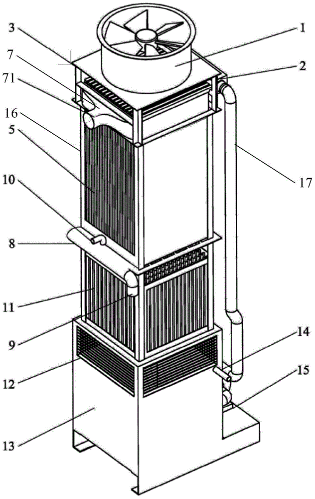
[0093] figure 1 An evaporative condenser is shown, which is a structural type in which air and water flow countercurrently on the outer wall of the heat exchange plate. The periphery of the evaporative condenser should be closed except for the position of the tuyere. In order to show its internal structure, the surrounding walls are not drawn.
[0094] The evaporative condenser includes a frame 16 , a water tank 13 arranged at the bottom of the frame 16 , a water tank 2 , a water pump 15 , a water distribution assembly 3 and a heat exchange assembly 5 . The water distribution assembly 3 is formed with a first channel (not shown in the figure) for cooling water to flow. The water tank 13 is provided with a water filling port 14 . The water supply port 14 is used to supplement evaporated moisture. In this embodiment, the water tank 2 is a high-level water tank, which provides water source for the water distributor and receives water supply from the water pump 15 .
[0095] ...
Embodiment 2
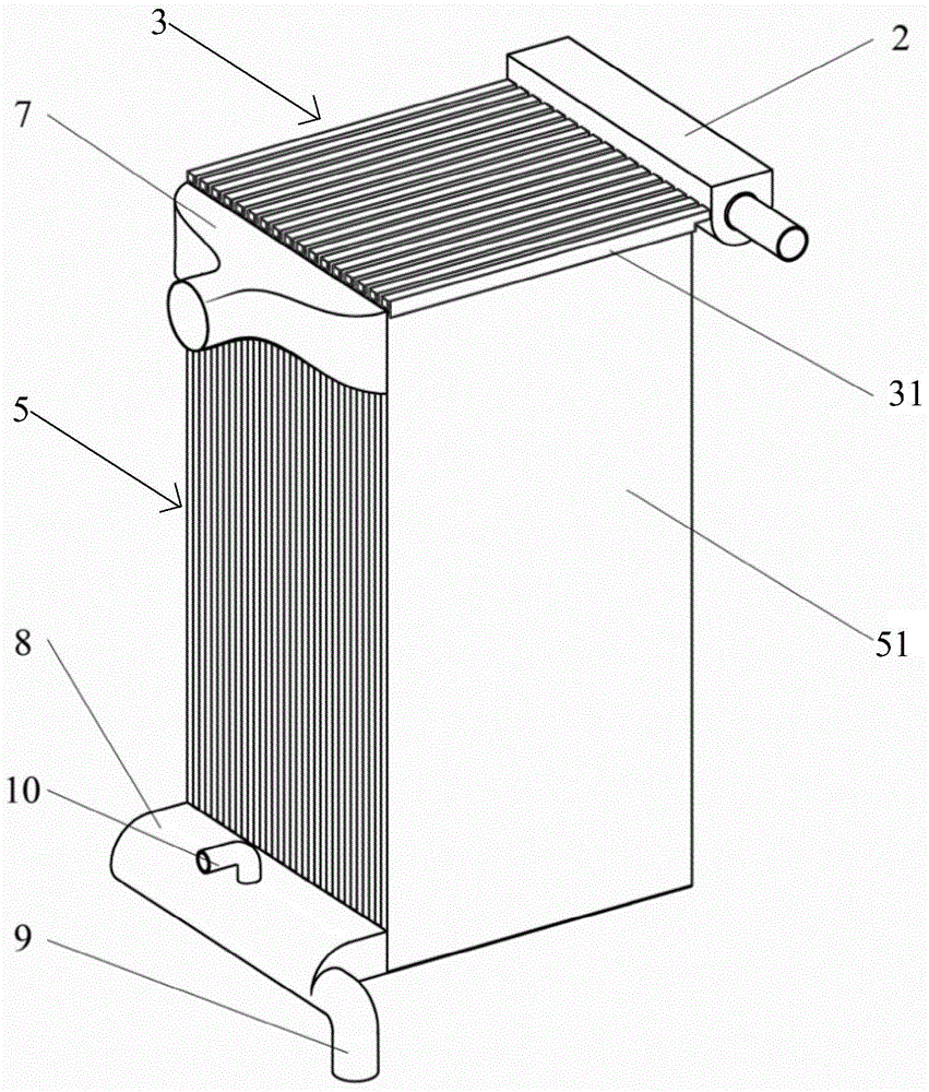
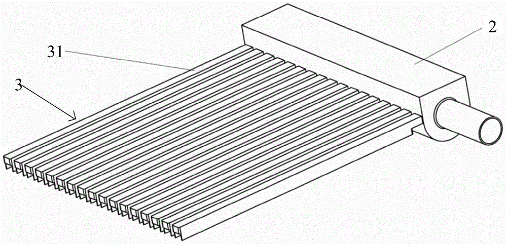
[0129] to combine Figure 7-9It should be understood that the structure of the evaporative condenser in this embodiment is basically the same as that of the evaporative condenser in Example 1, the difference being that the water distribution assembly 3' includes a water distribution body, and the water distribution body Formed in 31' is an annular flow channel (not shown in the figure) and several locking grooves 32' arranged side by side and spaced apart. The top of each heat exchange plate 51' is clamped in the clamping groove 32', and the bottom of the peripheral wall of each clamping groove 32' is provided with a comb-shaped channel 33 communicating with the annular flow channel ', the comb-toothed channel 33' is also in communication with the corresponding second channel.
[0130] At the same time, one end of the water distribution body 31' is connected to a water pump 15' through a connecting pipe 17', and the water pump 15' is arranged in the frame 16' near the water t...
PUM
 Abstract
Description
Claims
Application Information
 - R&D
- Intellectual Property
- Life Sciences
- Materials
- Tech Scout
- Unparalleled Data Quality
- Higher Quality Content
- 60% Fewer Hallucinations
Browse by: Latest US Patents, China's latest patents, Technical Efficacy Thesaurus, Application Domain, Technology Topic, Popular Technical Reports.
© 2025 PatSnap. All rights reserved.Legal|Privacy policy|Modern Slavery Act Transparency Statement|Sitemap|About US| Contact US: help@patsnap.com