
Rainfall field reconstruction method by integrating microwave link, disdrometer, rain gauge and weather radar

A raindrop spectrometer and microwave link technology, applied in the field of atmospheric science, can solve problems such as poor spatial representation, easy to miss the center of heavy rain, and limited distribution density of stations, and achieve the effect of improving accuracy

Active Publication Date: 2017-01-11
NAT UNIV OF DEFENSE TECH
View PDF7 Cites 22 Cited by
  • Summary
  • Abstract
  • Description
  • Claims
  • Application Information

AI Technical Summary

Problems solved by technology

Weather radar can provide spatially continuous precipitation dynamic observation information and realize real-time monitoring and early warning of precipitation. However, the radar echo intensity Z is affected by various factors such as ground objects, terrain clutter, and propagation paths, and is different from the rainfall intensity I. The relationship between them is not stable, making the accuracy of local precipitation measurement not high
The rain gauge can obtain high-precision single-point precipitation intensity and cumulative precipitation, but it can only reflect the precipitation information of limited discrete points, and the station distribution density is limited, and the spatial representation is poor. It is often easy to miss the center of the heavy rainstorm and cannot obtain the space of precipitation fine distribution
The raindrop spectrometer can obtain the raindrop spectrum characteristics of precipitation, and can describe the precipitation in detail, with high measurement accuracy, but the spatial representation is limited

Method used


Image

  • Rainfall field reconstruction method by integrating microwave link, disdrometer, rain gauge and weather radar
  • Rainfall field reconstruction method by integrating microwave link, disdrometer, rain gauge and weather radar
  • Rainfall field reconstruction method by integrating microwave link, disdrometer, rain gauge and weather radar

Examples


Embodiment Construction

[0026] Embodiments of the present invention will be described in detail in conjunction with the accompanying drawings.

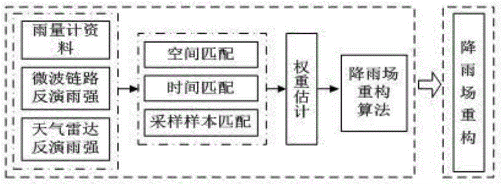
[0027] Such as figure 2 As shown, the algorithm of multi-source rainfall data reconstruction precipitation field of the present invention comprises the following steps:

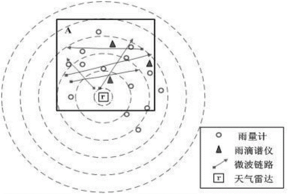
[0028] 1. Select the coverage area of ​​microwave link network, raindrop spectrometer, some rain gauges and weather radar synchronous observation, and carry out discrete grid;

[0029] 2. Do space matching and time matching for the precipitation data, and use the inverse distance interpolation method to interpolate to obtain gridded data;

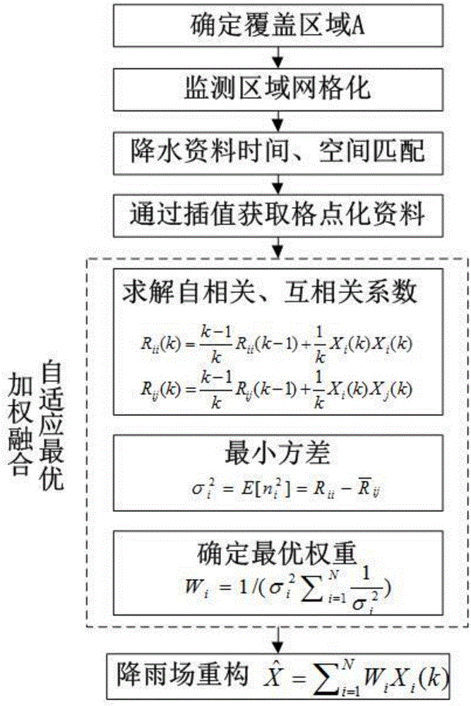
[0030] 3. Through the fusion algorithm of adaptive optimal weighting as an example, according to the observation values ​​under a certain time series, the optimal weight corresponding to each grid point is obtained by solving.

[0031] Such as image 3 As shown, the reconstruction process taking the adaptive optimal weighted fusion algorithm as an ex...


PUM


Abstract

The invention discloses a rainfall field reconstruction method by integrating microwave link, disdrometer, rain gauge and weather radar: selecting microwave link, disdrometer, rain gauge and weather radar to synchronously observe areas covered and make disperse lattices; making space matching and time matching over data of rainfall intensity synchronously observed by disdrometer, rain gauge and weather radar and making interpolation by inverse distance interpolation to draw lattice data; reconstructing rainfall field by lattice data of rainfall intensity synchronously observed by microwave link, disdrometer, rain gauge and weather radar: evaluating autocorrelation coefficient and cross-correlation coeffi-cient of data of rainfall intensity synchronously observed by microwave link, disdrometer, rain gauge and weather radar by recursion of estimated value in time domain to further determine variance of microwave link, disdrometer, rain gauge and weather radar; estimating and determining best weight of four kinds of data of rainfall intensity by minimum variance to realize rainfall field reconstruction.

Description

technical field [0001] The invention belongs to the field of atmospheric science, and specifically relates to synchronous measurement of a microwave link, a raindrop spectrometer, a rain gauge and a weather radar, optimizes multi-source rainfall data through a data fusion method, and realizes the reconstruction of a rainfall field. Background technique [0002] Accurate estimation of the spatial distribution of precipitation is of great significance for flood monitoring, early warning of geological disasters, hydrological analysis of watersheds, and design of water conservancy projects. Weather radar can provide spatially continuous precipitation dynamic observation information and realize real-time monitoring and early warning of precipitation. However, the radar echo intensity Z is affected by various factors such as ground objects, terrain clutter, and propagation paths, and is different from the rainfall intensity I. The relationship between them is unstable, which makes...

Claims


Application Information

Patent Timeline
IPC IPC(8): G01W1/14G01S13/95G01W1/00G06F19/00
CPCG01S13/95G01W1/00G01W1/14G16Z99/00Y02A90/10
Inventor 薛杨高太长刘西川宋堃胡云涛
Owner NAT UNIV OF DEFENSE TECH
Learn More