A multi-scan drive axis movable polygonal mirror optical path direct writing device

A drive shaft and polygon mirror technology, applied in the field of direct writing exposure, can solve the problems of inability to produce super large plates, inaccurate focusing and positioning, air leakage of vacuum suction cups, etc., and achieve the effects of reducing deformation, high precision, and preventing edge warping.

Active Publication Date: 2017-11-17
JIANGSU YSPHOTECH INTERGRATED CIRCUIT EQUIP CO LTD
View PDF7 Cites 1 Cited by
  • Summary
  • Abstract
  • Description
  • Claims
  • Application Information

AI Technical Summary

Problems solved by technology

[0012] In view of the above problems, the present invention provides a vacuum chuck and a multi-scanning drive shaft movable multi-prism optical path direct writing device containing the vacuum chuck, to solve the problem that the existing technology cannot produce super large boards, vacuum chuck air leakage, focusing and Inaccurate positioning and other issues

Method used


Image

  • A multi-scan drive axis movable polygonal mirror optical path direct writing device
  • A multi-scan drive axis movable polygonal mirror optical path direct writing device
  • A multi-scan drive axis movable polygonal mirror optical path direct writing device

Examples


Embodiment 1

[0079] Example 1: Vacuum suction cup

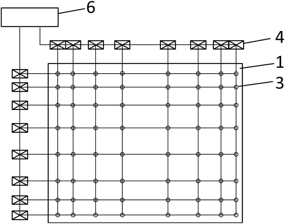
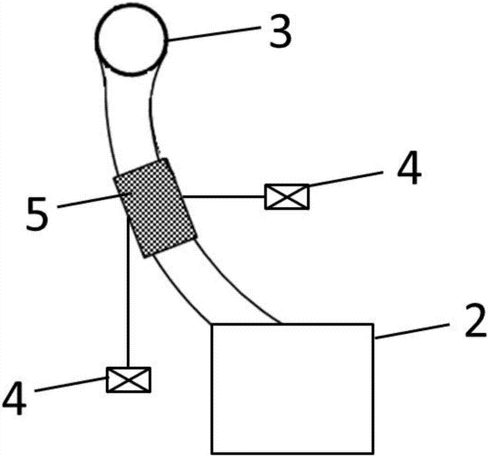
[0080] The vacuum chuck structure of the present invention is as Figure 1-2 shown.

[0081] The vacuum suction cup of the present invention includes a suction cup main body 1 and a vacuum generating device 2; a certain number of air holes 3 are distributed on the suction cup main body 1 in the form of rows and columns, each row of air holes 3 corresponds to a relay 4, and each column of air holes also corresponds to a relay ; Between each air hole 3 and the vacuum generating device 2, an air hole switch 5 is connected; the air hole switch 5 is connected with the relay in the row of the air hole and the relay in the column of the air hole at the same time.

[0082] Each relay is connected with the general control device 6 . The air hole switch is located on the vacuum pipeline connected between the air hole and the vacuum generating device. The air hole switch may be an electromagnetic switch. The air holes may be evenly distributed o...

Embodiment 2

[0084] Example 2: Vacuum suction cup

[0085] The vacuum chuck of the present embodiment, in embodiment 1 such as Figure 1-2 A modified version of the vacuum cup shown.

[0086] The air holes 3 on the main body 1 of the suction cup are distributed sparsely in the middle and densely around.

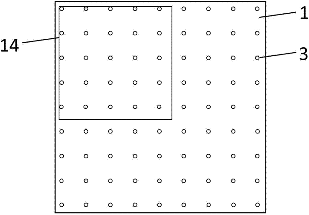
[0087] In traditional vacuum chucks, the air holes are generally evenly distributed. When producing a small PCB, it is possible that after the substrate 14 is placed on the main body of the suction cup, a certain edge of the substrate is located far away from the air holes on both sides (such as image 3 As shown), the edge part will be lifted due to the lack of vacuum suction, which will affect the production. After adopting the distribution form of the present invention, which is sparse in the middle and dense around, as Figure 4-5 As shown, when a small substrate is placed on the vacuum chuck, choose to place the substrate close to the edge of the suction cup body. Move to the nea...

Embodiment 3

[0091]Embodiment 3: Direct writing device with movable polygonal mirror and optical path with dual scanning drive shafts

[0092] A direct writing device with a movable polygonal mirror optical path with dual scanning drive shafts containing two moving components is taken as an example for illustration.

[0093] Such as Figure 6-7 Shown is a double-scan drive shaft movable polygonal mirror optical path direct writing device containing a vacuum chuck of the present invention.

[0094] The dual-scan drive shaft movable polygonal mirror optical path direct writing device includes a base 7, a polygonal mirror optical path 8, a stepping drive shaft 9, a plurality of moving components, a vacuum chuck 10, a connecting plate 15, and a camera 16; each moving component includes a scanning Drive the Y-axis 12 and a lifting drive Z-axis 13; the vacuum chuck 10 is located above the moving assembly.

[0095] The polygonal mirror optical path 8 is connected with the stepping drive shaft 9...


PUM

PropertyMeasurementUnit
areaaaaaaaaaaa
areaaaaaaaaaaa

Abstract

The invention discloses a multi-scanning-driving-shaft movable polygon-prism light-path directly-writing device, and belongs to the technical field of directly-writing exposure. According to the multi-scanning-driving-shaft movable polygon-prism light-path directly-writing device, a vacuum suction cup structure is mainly improved, and the problem that when a small plate is produced, insufficient absorption force is caused by air leakage is solved. Further, as air holes in the suction cup are distributed in the mode that the middle is thin, and the periphery is thick, the problem that edge of the plate is cocked is effectively solved, the number of the air holes is saved, and the cost is reduced. By means of the multi-scanning-driving-shaft movable polygon-prism light-path directly-writing device, an extra-large plate can be produced; the lower portion of the suction cup is connected with a plurality of moving assemblies, moving shafts of the multiple moving assemblies synchronously move, and the exposure accuracy and the operating stability are improved. Meanwhile, the accurate image exposure position can be guaranteed by improving the partition para-position focusing method, and image exposure is clear.

Description

technical field [0001] The invention relates to a multi-scan drive shaft movable polygonal mirror optical path direct writing device, which belongs to the technical field of direct writing exposure. Background technique [0002] PCB (printed circuit board) is the support body of electronic components, and also the carrier of electrical connection of electronic components. Common PCB production equipment includes traditional exposure machines, multi-prism structure laser direct writing exposure machines, DMD structure laser direct writing exposure machines, etc. The laser direct writing exposure machine can directly image the image on the PCB board. Compared with the traditional exposure machine, it does not need to use film, and the formed image is clearer. [0003] As the market's functional requirements for PCB boards are getting higher and higher, PCB boards are becoming more and more complex, and system compatibility is higher. Sometimes a large substrate is required. H...

Claims


Application Information

Patent Timeline
Patent Type & Authority Patents(China)
IPC IPC(8): G03F7/20
CPCG03F7/70366G03F7/70383G03F7/704
Inventor 李显杰
Owner JIANGSU YSPHOTECH INTERGRATED CIRCUIT EQUIP CO LTD
Why Eureka
Try Eureka