Power supply screen flash plate circuit

A technology of power supply screen and circuit, which is applied in the direction of electric lamp circuit layout, electric light source, light source, etc., can solve the problems of large volume, large installation space, poor reliability, etc., achieve high parameter accuracy and stability, and are not easy to damage the circuit, frequency Easy to adjust the effect

Active Publication Date: 2017-01-11
LIUZHOU RAILWAY VOCATIONAL TECHN COLLEGE
View PDF12 Cites 1 Cited by
  • Summary
  • Abstract
  • Description
  • Claims
  • Application Information

AI Technical Summary

Problems solved by technology

[0003] 1. The flash power supply circuit board does not use integrated circuits, which is bulky and takes up a lot of space for installation;
[0004] 2. Discrete components are used, which are easily damaged and have poor reliability;
[0005] 3. The flash frequency is adjusted by two potentiometers, if the adjustment is too much, the circuit will be easily damaged;
[0006] 4. The size of the flash frequency is not intuitive, only by feeling;
[0007] 5. The stability of the flash power supply is poor, which affects the normal operation of the signal equipment
[0008] At present, when railway colleges and universities are simulating the railway site, in order to improve the efficiency of the experiment, students need to intuitively understand the working conditions of the equipment and the parameters related to the measurement through observation and hands-on operation of the equipment. , the adjustment of the flash power frequency is inconvenient, the current output power frequency cannot be observed intuitively, and the equipment is easily damaged, the reliability is poor, the experimental effect cannot meet the needs of teaching, and it is not suitable for the needs of signal professional experiment training

Method used


Image

  • Power supply screen flash plate circuit
  • Power supply screen flash plate circuit
  • Power supply screen flash plate circuit

Examples


Embodiment Construction

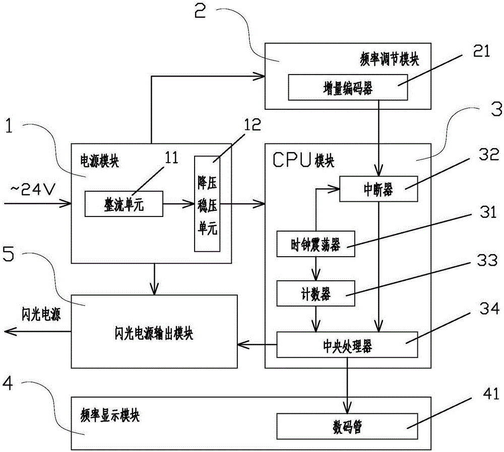
[0043] A power screen flash board circuit, such as figure 1 As shown, it includes a power supply module 1, a frequency adjustment module 2, a CPU module 3, a frequency display module 4 and a flash power output module 5;

[0044] The input end of the power supply module 1 is connected to 24V alternating current, and the output end is respectively connected to the input end circuit of the frequency adjustment module 2, the CPU module 3 and the flash power output module 5, and the output end of the frequency adjustment module 2 is connected to the input end of the CPU module 3 Circuit connection, the output end of the CPU module 3 is connected to the input end circuit of the frequency display module 4 and the flash power output module 5, and the output end of the flash power output module 5 is connected to an external device;

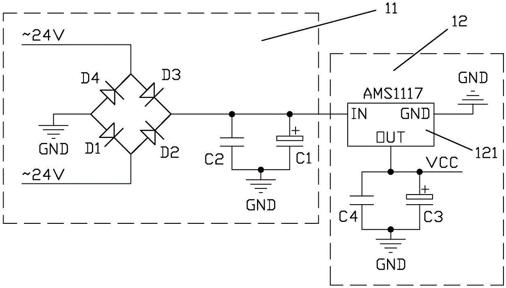
[0045] The power supply module 1 is used to reduce the input 24V AC power to a stable and reliable 5V DC power, and deliver the 5V DC power to the frequen...


PUM


Abstract

A power supply screen flash plate circuit comprises a power module, a frequency regulating module, a CPU module, a frequency display module and a flashing power source output module, wherein the power module reduces input 24V alternating current into stable and reliable 5V direct current so as to provide working power for modules, the frequency regulating module produces and sends pulses to the CPU module, the CPU module receives pulse signals and counts the frequencies of a flashing power source, sends the counted frequency data to the frequency display module for display and meanwhile controls the flashing power source output module to output flashing frequencies, and the frequency regulating module comprises an incremental encoder and can adjust the flashing frequencies at any time. The power supply screen flash plate circuit can provide a 24V alternating-current flashing power source required by a real railway field to achieve power on-off ratio of 1 to 1, the parameter accuracy and the stability are higher, and high reliability, few breakdowns, simple circuit, small size and working stability are achieved by adopting the integrated circuit, and practical teaching about railway signal power equipment in railway academies can be improved.

Description

technical field [0001] The invention relates to railway signal technology, a power supply system of railway signal equipment, and a stable technology of signal power supply, in particular to a power supply screen flash board circuit that provides 24V AC flash power required by the railway site. Background technique [0002] The signal power supply panel is a system that provides power for signal equipment. The stability, reliability and safety of the power supply provided by the signal power supply panel will directly affect the work of signal equipment. For a long time, the flash power supply of the signal power screen has the following shortcomings: [0003] 1. The flash power supply circuit board does not use integrated circuits, which is bulky and takes up a lot of space for installation; [0004] 2. Discrete components are used, which are easily damaged and have poor reliability; [0005] 3. The flash frequency is adjusted by two potentiometers, if the adjustment i...

Claims


Application Information

Patent Timeline
Patent Type & Authority Applications(China)
IPC IPC(8): G09B23/18H05B37/02
CPCG09B23/188H05B47/10Y02B20/40
Inventor 张娟娟黄斌关琼赵宁吴建军
Owner LIUZHOU RAILWAY VOCATIONAL TECHN COLLEGE
Why Eureka
Try Eureka