Power distribution network voltage reactive power compensation equipment management system

A technology for compensating equipment and voltage reactive power, applied in reactive power compensation, reactive power adjustment/elimination/compensation, system integration technology, etc. The equipment lacks a unified management platform and other issues

Inactive Publication Date: 2017-01-11
南京易司拓电力科技股份有限公司
View PDF4 Cites 1 Cited by
  • Summary
  • Abstract
  • Description
  • Claims
  • Application Information

AI Technical Summary

Problems solved by technology

[0002] In the past, reactive power compensation planning calculations were calculated using empirical formulas (20-40% of the load capacity). Since the empirical formulas only give a range, it is impossible to determine the specific configuration capacity, let alone the specific configuration location.
Moreover, with the change of grid structure in the later stage, it is impossible to grasp the configuration of reactive power compensation under the condition of the existing grid in time, and whether it can meet the requirements of reactive power management
[0003] At present, the reactive power compensation equipment on the substation side can grasp its operation status in a timely manner. However, due to the lack of a unified management platform for the reactive power compensation equipment in the distribution network, most of them only rely on the on-site inspection of the power supply station and team personnel, resulting in the inability to timely understand the file ledger and operation status.

Method used


Image

  • Power distribution network voltage reactive power compensation equipment management system

Examples


Embodiment Construction

[0014] In order to make the object, technical solution and advantages of the present invention clearer, the present invention will be further described in detail below in conjunction with the accompanying drawings and embodiments. It should be understood that the specific embodiments described here are only used to explain the present invention, not to limit the present invention.

[0015] Unless the context clearly states otherwise, the number of elements and components in the present invention can exist in a single form or in multiple forms, and the present invention is not limited thereto. Although the steps in the present invention are arranged with labels, they are not used to limit the order of the steps. Unless the order of the steps is clearly stated or the execution of a certain step requires other steps as a basis, the relative order of the steps can be adjusted. It can be understood that the term "and / or" used herein refers to and covers any and all possible combina...


PUM


Abstract

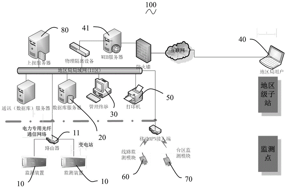
The invention provides a power distribution network voltage reactive power compensation equipment management system. The power distribution network voltage reactive power compensation equipment management system comprises a plurality of monitoring devices, a database server, a management terminal, and a regional bureau user terminal, and is characterized in that the plurality of monitoring devices are used for monitoring the operating state of reactive power compensation equipment in a substation, the database server and the management terminal are in communication connection with the plurality of monitoring devices through a regional bureau local area network, and the regional bureau user terminal is in communication connection with the regional bureau local area network through the Internet; each monitoring device is connected to the regional bureau local area network through an electric power dedicated optical fiber, a WEB server is arranged between the regional bureau local area network and the Internet, and the management terminal and the regional bureau user terminal realize communication connection therebetween through the regional bureau local area network and the Internet. The beneficial effects lie in that the power distribution network voltage reactive power compensation equipment management system can perform unified management and monitoring on the operating state of reactive power compensation equipment in each monitored substation through the regional bureau local area network.

Description

technical field [0001] The invention relates to a management system for voltage and reactive power compensation equipment of a power distribution network. Background technique [0002] In the past, reactive power compensation planning calculations were calculated using empirical formulas (20-40% of the load capacity). Since the empirical formulas only give a range, it is impossible to determine the specific configuration capacity, let alone the specific configuration location. Moreover, with the change of grid structure in the later stage, it is impossible to grasp the configuration of reactive power compensation under the condition of the existing grid in time, and whether it can meet the requirements of reactive power management. [0003] At present, the reactive power compensation equipment on the substation side can grasp its operation status in a timely manner. However, due to the lack of a unified management platform for the reactive power compensation equipment in the...

Claims


Application Information

Patent Timeline
Patent Type & Authority Applications(China)
IPC IPC(8): H02J3/18H02J13/00
CPCH02J13/0082H02J3/18Y02E40/30Y04S10/16Y04S10/22Y04S40/124Y04S40/128Y02E40/70Y02E60/00
Inventor 罗定志陈俊长查鸣屈永刚罗耀强张珍凤
Owner 南京易司拓电力科技股份有限公司
Why Eureka
Try Eureka