Method for calibrating, compensating and self-correcting parameters of optical module

A parameter calibration and parameter compensation technology, which is applied in the field of compensation and self-correction, and optical module parameter calibration, can solve the problems of inconvenient operation, high cost, and many pins, so as to improve accuracy and reliability, improve adaptability, and personnel Participation workload reduction effect

Inactive Publication Date: 2017-01-11
WUXI ELECTRONICS & INSTR IND
View PDF8 Cites 39 Cited by
  • Summary
  • Abstract
  • Description
  • Claims
  • Application Information

AI Technical Summary

Problems solved by technology

[0003] In order to realize the monitoring and diagnosis of optical modules, the main chip of some optical modules will contain calibration and compensation registers, but some do not include these registers, and the inclusion of calibration and compensation registers does not mean that internal self-diagnosis can be realized. On the one...

Method used


Image

  • Method for calibrating, compensating and self-correcting parameters of optical module
  • Method for calibrating, compensating and self-correcting parameters of optical module
  • Method for calibrating, compensating and self-correcting parameters of optical module

Examples


Embodiment

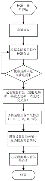
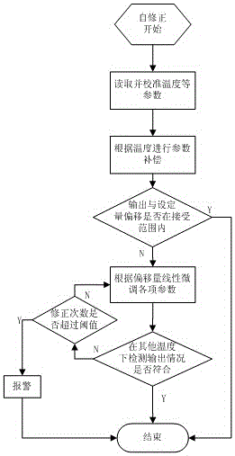
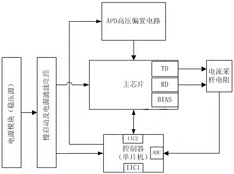
[0019] Embodiment: This embodiment is specifically described in combination with a preferred solution. The optical module in this embodiment takes 10G PON as an example. The specific implementation methods of optical module parameter calibration, compensation and self-correction are as follows: Step 1, start the optical module, burn the controller program and complete the initial configuration, confirm the host computer Communication with the controller is normal; step 2, obtain the read value of each monitoring parameter, read the temperature, voltage, transmitted light power, received light power, and bias current through the registers in the main chip. The specific operation is powered by the MCU program After initialization, it is automatically completed, stored in real-time variables, and uploaded to the upper computer regularly; step 3, obtain the actual value of each monitoring parameter, the temperature value is read out by the instrument of the high and low temperature ...


PUM


Abstract

The invention relates to the technical field of optical fiber communication, and particularly discloses a method for calibrating, compensating and self-correcting parameters of an optical module. The method comprises the steps of: (1) parameter calibration, i.e., reading read-out values of each monitored parameter of the optical module at different temperatures, acquiring corresponding actual values, obtaining a calibration formula and calibrating each monitored parameter by the calibration formula; (2) parameter compensation, i.e., by using a module output at the normal temperature as a reference value, regulating parameter setting of an optical module register to enable an actual module output to be approximate to the reference value, and fitting into a compensation formula; and (3) parameter self-correction, i.e., comparing an output value of each calibrated parameter with an ideal value, and if a large deviation exists, fine regulating the parameter according to a deviation direction, correcting an output effect, and regulating a parameter value of the compensation formula in the step (2). According to the method disclosed by the invention, workload of a worker is reduced, and accuracy and reliability of each parameter index of the optical module are improved.

Description

Technical field [0001] The invention relates to the technical field of optical fiber communication, in particular to a method for optical module parameter calibration, compensation and self-correction. Background technique [0002] At present, there are more and more types of optical modules used in various networks, and the speed is getting faster and faster. Under the increasing network demand, the requirements for the optical module itself are getting higher and higher, and the products of the optical module are constantly increasing. Development towards standardization, miniaturization and intelligence. With the increase in the demand for optical module products and the improvement of various index requirements, high requirements are put forward for the accuracy and reliability of various parameter indexes of the optical module. [0003] In order to realize the monitoring and diagnosis of the optical module, the main chip of some optical modules will contain calibration and co...

Claims


Application Information

Patent Timeline
IPC IPC(8): H04B10/07H04B10/075
CPCH04B10/07H04B10/075
Inventor 马晓贤吴照明周佳贤俞文忠
Owner WUXI ELECTRONICS & INSTR IND
Why Eureka
Try Eureka