Check patentability & draft patents in minutes with Patsnap Eureka AI!

Unloading frame of cutting machine with automatic unloading function

An automatic unloading and material cutting machine technology, applied in the field of unloading racks, can solve the problems of reducing the processing efficiency of plastic parts and increasing equipment costs, and achieve the effect of reducing equipment costs and improving processing efficiency

Active Publication Date: 2017-01-18
英力电子科技(重庆)有限公司
View PDF6 Cites 0 Cited by
  • Summary
  • Abstract
  • Description
  • Claims
  • Application Information

AI Technical Summary

Problems solved by technology

The technical problem of the above-mentioned unloading rack is: when the processed plastic parts are sent out from the cutting machine through the unloading rack, it is necessary to additionally set up a manipulator to grab the plastic parts and send the plastic parts to the next processing station, so that not only Due to the addition of additional manipulators, the cost of equipment is increased, and the processing efficiency of plastic parts is reduced

Method used


Image

  • Unloading frame of cutting machine with automatic unloading function

Examples


Embodiment Construction

[0016] The present invention will be described in further detail below by means of specific embodiments:

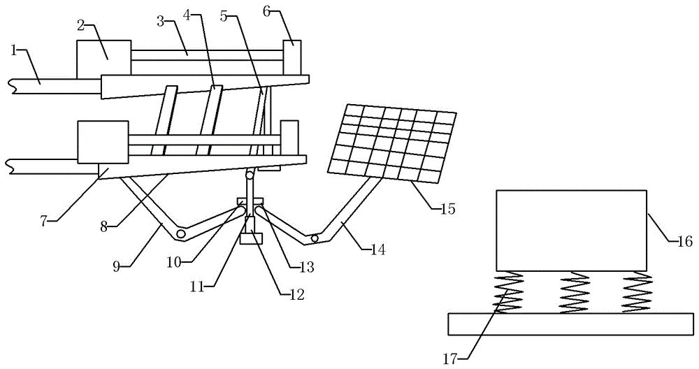
[0017] The reference signs in the drawings of the description include: guide rail 1, cylinder 2, piston rod 3, support plate 4, delivery rod 5, connection seat 6, delivery rail 7, inclined plane 8, first swing rod 9, first protrusion 10 , pillar 11, sleeve 12, second protrusion 13, second swing rod 14, transmission member 15, receiving plate 16, support spring 17.

[0018] as attached figure 1 As shown in the unloading frame of the cutting machine with automatic unloading function, two guide rails 1 are fixed horizontally and parallelly, and each guide rail 1 is provided with a conveying rail 7 that can slide along the length direction of the guide rail 1, and the guide rail 1 is used for guiding when the conveyor rail 7 moves. The end of the delivery rail 7 away from the guide rail 1 is provided with a connecting seat 6, the connecting seat 6 is fixed to the end of a p...


PUM


Abstract

The invention discloses an unloading frame of a cutting machine with an automatic unloading function. The unloading frame comprises two parallel guide rails which are both fixedly arranged, wherein a conveying rail capable of sliding in the length direction of each guide rail is arranged on each guide rail, the bottom surface of each conveying rail is an oblique surface which gradually tilts upwards in an outward conveying direction, a conveying rod is arranged below each conveying rail, the oblique surface at the bottom of each conveying rail can be abutted with the upper rod surface of the conveying rod, two support columns are separately arranged at the lower parts of the two ends of each conveying rod, the lower parts of the support columns are connected with the upper parts of compressed springs, the lower parts of the compressed springs are connected with a base, first projections are arranged on the support columns, V-shaped first swinging rods are arranged at the sides, close to the guide rails, of the support rods, the middles of the first swinging rods are hinged to first shafts, one ends of the first swinging rods can be abutted with the lower parts of the first projections, and the other ends of the first swinging rods can be abutted with the lower parts, close to the guide rails, of plastic components placed on a support plate so as to tilt the parts, close to the guide rails, of the plastic components upwards.

Description

technical field [0001] The invention relates to the technical field of processing computer accessories, in particular to an unloading rack of a material cutting machine with an automatic unloading function. Background technique [0002] The plastic cutting machine adopts a double-cylinder hydraulic structure and is equipped with a travel switch safety protection device. It is mainly used in the plastic industry to process various large soft plastics and large oil drums. It has the characteristics of strong material cutting ability, wide application range and convenient operation. The loading and unloading rack is an important component structure of the plastic cutting machine. Some accessories of the computer, such as the casing of the main chassis and the casing of the keyboard, are made of plastic parts. [0003] The existing unloading frame of the plastic cutting machine used for computer plastic accessories, its main structure includes: two parallel and fixed guide rai...

Claims


Application Information

Patent Timeline
IPC IPC(8): B26D7/32B26D7/27
CPCB26D7/27B26D7/32
Inventor 向虎
Owner 英力电子科技(重庆)有限公司
Features
  • R&D
  • Intellectual Property
  • Life Sciences
  • Materials
  • Tech Scout
  • Unparalleled Data Quality
  • Higher Quality Content
  • 60% Fewer Hallucinations
Learn More